Utrasonic flowmeter
- Summary
- Abstract
- Description
- Claims
- Application Information
AI Technical Summary
Problems solved by technology
Method used
Image


Examples
second embodiment
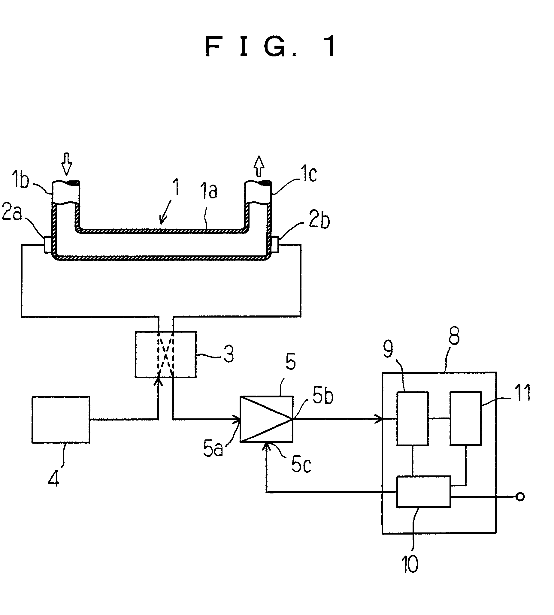
[0041] The CPU 10 picks up waveform data including one or more peak values P from the memory 11 in parallel with proceeding the above mentioned processing step. A peak value of a waveform datum obtained on the fluid containing no bubbles is to be defined as a screened peak value by the means of the first or the second embodiment as mentioned hereinbelow. The screened peak value is compared with the peak values preset on the CPU 10. Depending upon whether the result obtained by such comparison is negative or positive, the amplifier 5 is controlled in analog or digital form by delivering the gain control signal to the gain control terminal 5c of the amplifier. The gain will thus be modified or controlled. The magnitude of the amount of the amplification of the gain is, for example, 1-2 dB.
[0042] The difference between the above mentioned gain control system and the closed loop control system will now be described. Generally, in the closed loop control system, the present value of the ...
first embodiment
[0047] The First Embodiment
[0048] The first embodiment is the most practicable method that is applicable to the circumstance good for the measurement. In such method, the maximum value of the peak values present on the predetermined time interval is regarded as a peak value obtained through the fluid with no bubbles.
[0049] The CPU compares the adjacent peak values present on the predetermined time interval each other and select the relatively larger one. After all peaks are compared, the peak of maximum value on the time interval will be obtained, and the obtained maximum value is stored as the screened peak value, and compare it with the preset peak value. The steps to be effected in succession are the same as those described above.
[0050] Generally, the switching operation of the switch 3 has substantially no influence on the peak value P. Further, the peak value P has substantially no opportunities for attenuation while a little or no bubbles are included in the fluid. Thus a plur...
third embodiment
[0060] The Third Embodiment
[0061] The third embodiment represent an example of the control operation of the amplified gain of the amplifier 5 employed in the systems of the first and the second gain control type of the ultrasonic transducers according to the present invention. In this embodiment, the rates of increasing and decreasing of the gain are differentiated upon controlling the gain of the amplifier.
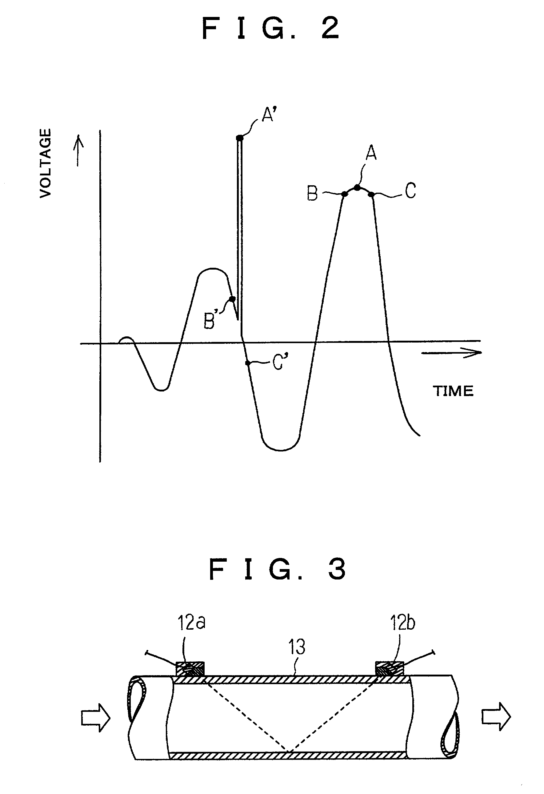
[0062] Generally in the flow rate measuring system independent of the magnitude of the received signal, the information on the waveform is utilized, so that the substantial variation of the received waveform is not preferable in view of ascertaining the waveform saturation. The term "waveform saturation" means the situation in which the waveform exceeds the limits of measurement.
[0063] When the output from the detector is decreased due to the drop of the temperature of the liquid, and thus it become necessary to increase the gain of the amplifier 5, the gain increasing rate is de...
PUM
 Abstract
Description
Claims
Application Information
 - R&D Engineer
- R&D Manager
- IP Professional
- Industry Leading Data Capabilities
- Powerful AI technology
- Patent DNA Extraction
Browse by: Latest US Patents, China's latest patents, Technical Efficacy Thesaurus, Application Domain, Technology Topic.
© 2024 PatSnap. All rights reserved.Legal|Privacy policy|Modern Slavery Act Transparency Statement|Sitemap