Stator

a technology of rotating shafts and rotating shafts, which is applied in the direction of dynamo-electric components, dynamo-electric machines, and magnetic circuit shapes/forms/construction, etc., can solve the problems of unable to achieve magnetic flux in the winding head of the exciting coil, and contribute to the torque of the rotor, so as to improve the performance of the excitation coil, improve the performance data, and reduce the effect of toleran

Inactive Publication Date: 2002-10-17
ROBERT BOSCH GMBH
View PDF0 Cites 49 Cited by
  • Summary
  • Abstract
  • Description
  • Claims
  • Application Information

AI Technical Summary

Benefits of technology

0004] In contrast, the stator according to the invention having the characterizing features in claim 1 has the advantage that a stator can be produced in simple fashion that makes smaller tolerances possible and has improved performance data, such as a higher slot fill factor of the excitation coils, less space required to install the motor, reduced stop torques, and higher torque, for example.
0005] Advantageous further developments and improvements of the stator named in claim 1 are possible due to the measures listed in the dependent claims.
0006] It is advantageous that a pole shoe is made of magnetically soft solid material, because a magnetic stray flux of a winding head of an exciting coil can then be directed in all spacial directions in defined fashion and contribute to the magnetic excitation.
0007] It is further advantageous that a coil insulating frame is located on the pole shoe, because a coil can then be wound in simple fashion.
0008] A coil can be electrically connected to an external power source or electrical control in advantageous fashion if an electrical connecting element is integrated in the coil insulating frame.

Problems solved by technology

This has the disadvantage, however, that a magnetic flux in the winding head of the exciting coil cannot be directed in defined fashion, and therefore does not contribute to the torque of the rotor, nor is there a gap in the foot of the tooth.

Method used


Image

  • Stator
  • Stator
  • Stator

Examples


Embodiment Construction

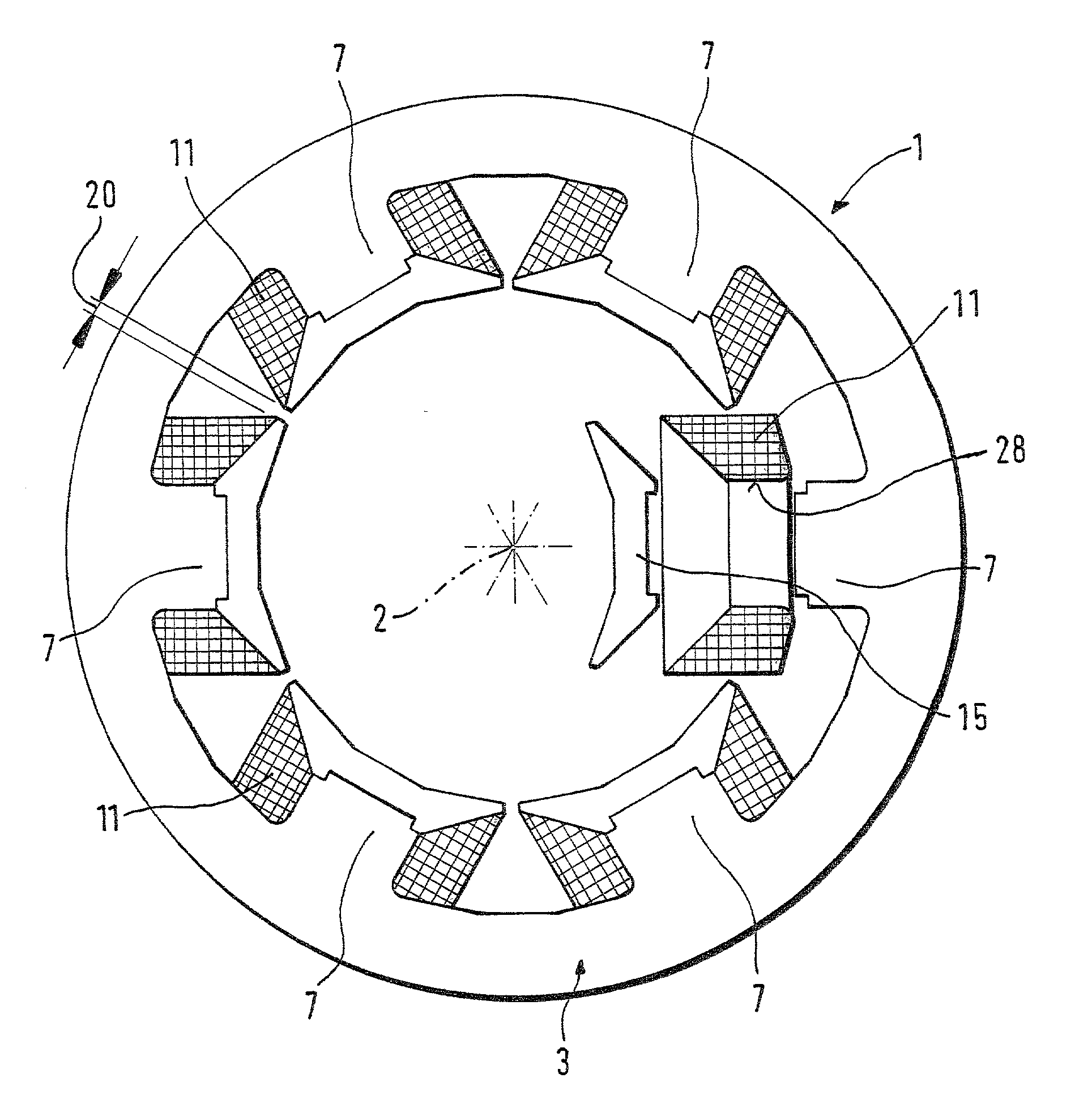
[0014] FIG. 1 shows a stator 1, according to the invention, of an electrical machine, such as an internal rotor motor, for example. The stator 1 is formed by a stator ring 3 that comprises at least one stator pole tooth 7 and a centerline 2. The stator ring 3 is made of a solid material, or it is laminated. The, e.g., six stator pole teeth 7 present, extending radially inward, are distributed evenly around the centerline 2.

[0015] A coil 11 is slid onto each stator pole tooth 7. These are preassembled coils 11, for example, e.g., "stoved-enamel" coils, or they are coils 11 wound onto a coil frame 28. The coils 11 can also be compound coils.

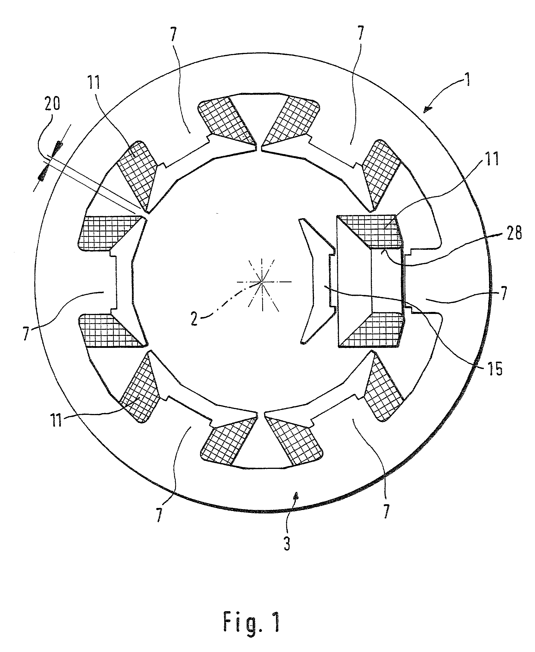
[0016] Each coil 11 is secured to the stator pole tooth 7 by means of one pole shoe 15. Each exposed end of a stator pole tooth 7 and each pole shoe 15 is designed in such a fashion, for example, that a press fit is produced when joined. Any other type of mounting is feasible.

[0017] A stator 1 is achieved as a result, the inner diameter of which ha...


PUM


Abstract

A stator according to the related art comprises preassembled coils that are slid onto stator pole teeth and secured to the respective stator pole tooth by means of a single part. This has the disadvantage, however, that a magnetic flux in the winding head of the exciting coil cannot be directed in defined fashion. A stator according to the invention comprises at least one pole shoe (15) that secures a coil (11) on a stator pole tooth (7).

Description

RELATED ART[0001] The invention is based on a stator according to the definition of the species in claim 1.[0002] A stator has already been made known in U.S. Pat. No. 5,089,730, onto the stator pole teeth of which a preassembled coil is slid. The coils are secured to the stator pole teeth by means of a single part.[0003] This has the disadvantage, however, that a magnetic flux in the winding head of the exciting coil cannot be directed in defined fashion, and therefore does not contribute to the torque of the rotor, nor is there a gap in the foot of the tooth.ADVANTAGES OF THE INVENTION[0004] In contrast, the stator according to the invention having the characterizing features in claim 1 has the advantage that a stator can be produced in simple fashion that makes smaller tolerances possible and has improved performance data, such as a higher slot fill factor of the excitation coils, less space required to install the motor, reduced stop torques, and higher torque, for example.[0005...

Claims


Application Information

Patent Timeline
Patent Type & Authority Applications(United States)
IPC IPC(8): H02K1/14H02K1/16H02K1/18H02K3/46H02K3/52
CPCH02K1/148H02K2203/12H02K3/522H02K1/14
Inventor HEIDRICH, MARKUS
Owner ROBERT BOSCH GMBH
Why Eureka
Try Eureka