Eureka AIR delivers breakthrough ideas for toughest innovation challenges, trusted by R&D personnel around the world.

External signature device for a pc with optical data input via the monitor

Inactive Publication Date: 2002-10-17
ESIGNUS
View PDF6 Cites 5 Cited by
  • Summary
  • Abstract
  • Description
  • Claims
  • Application Information

AI Technical Summary

Benefits of technology

[0001] The present invention relates to an external signature device for a PC with optical data input via the monitor, which provides fundamental novelty characteristics and substantial advantages with respect to methods known and used for these same purposes in the current state of the art.
[0008] Smart cards solve this problem by isolating the signature keys in a device external to the computer, so that the keys cannot be extracted from the card, and it is only possible to send data for its signature. This is a significant advance as it ensures that the signature key can never be stolen.
[0011] The system associated to the device described herein extends the functionality of smart cards, allowing users to view the data before signing them for purposes of verification, preventing the users from signing data which they do not wish to sign. Thereby, this device substantially improves the security of systems which rely on electronic signatures, and is immediately applicable to e-banking and e-commerce.

Problems solved by technology

In the present state of the art, the remote execution of monetary (or any other) transactions has the disadvantage of a possible undesired supplanting of identities.
The problem with this authentication system is that as the same password is always used, it is relatively easy to attack.
This means that even if an attacker were to intercept a document with its signature, it is not possible to generate the corresponding signature for a different document.

Method used


Image

  • External signature device for a pc with optical data input via the monitor
  • External signature device for a pc with optical data input via the monitor
  • External signature device for a pc with optical data input via the monitor

Examples


Embodiment Construction

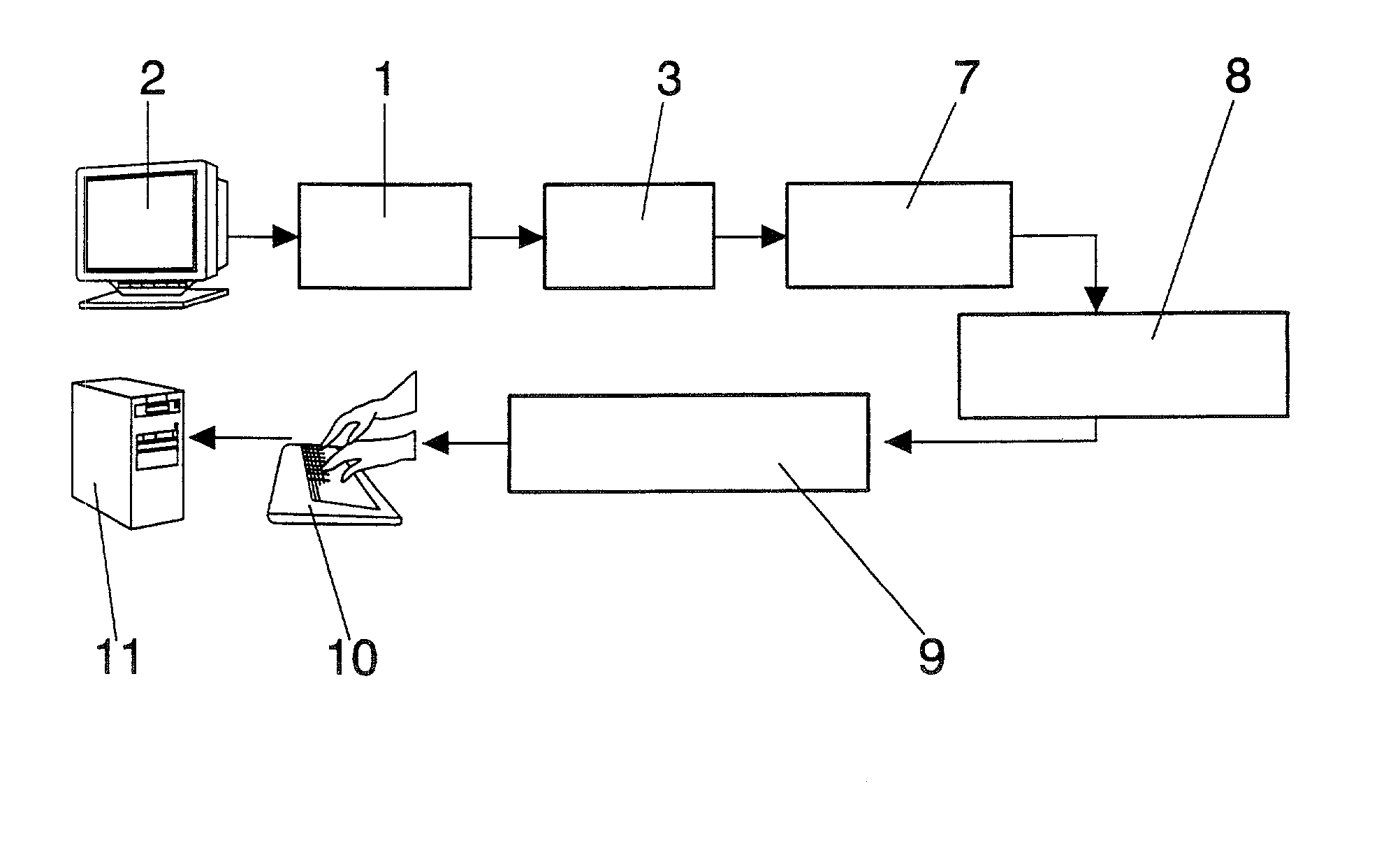
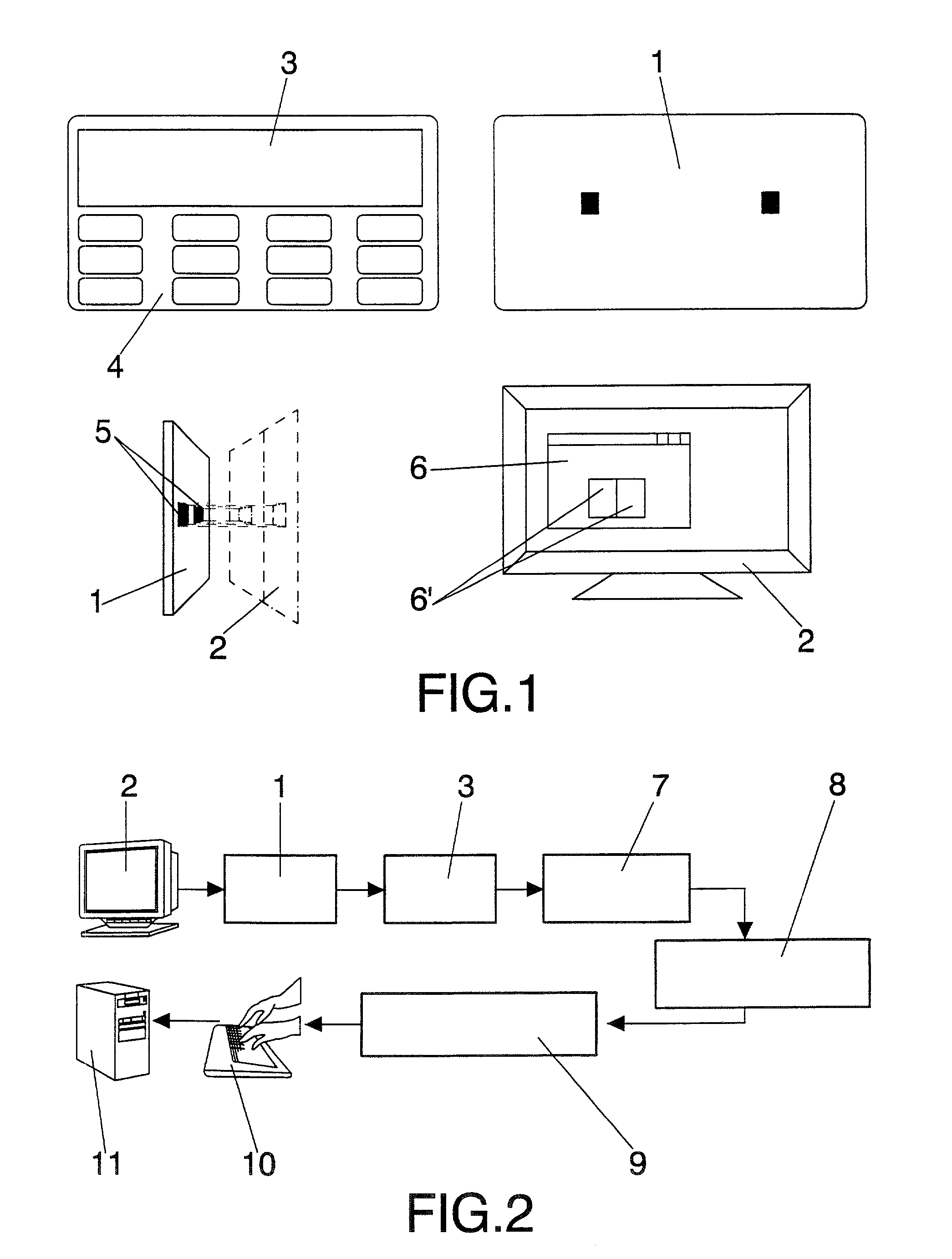
[0029] The detailed description of the preferred embodiment of the invention will be made with reference to the accompanying drawings, in which FIG. 1 shows the generic design for the external signer. In this representation the device is seen to include an optical data reception system (1), in which are incorporated the photo-detectors (5) meant to detect the optical signals sent by the monitor (2), with the label (6) indicating the specific transmission area from said monitor, which monitor may be of any known type (CRT, TFT or whichever other display technology); on its part, the alphanumerical display is shown with the label (3), while the keyboard is labeled (4). The signature system meant to process the signing operations for the received data has not been explicitly shown.

[0030] The signing procedure used by this device is schematically represented in the block diagram of FIG. 2. Firstly the signer is activated by entering a PIN on keyboard (4), then transmitting the data to b...


PUM


Abstract

A device is described for electronic signature of data which can be immediately applied in e-banking and e-commerce or in any system based on electronic signature, with an optical input for receiving data from any computer monitor and with a display for showing the data to be signed. In addition it has a keyboard for interaction with the user and a system for processing the electronic signature. The device is not re-programmable, so that it is immune to possible attacks from viruses or malicious software which could compromise the system security. Moreover, as the data to be signed are displayed the user knows what data he or she is actually signing.

Description

OBJECT OF THE INVENTION[0001] The present invention relates to an external signature device for a PC with optical data input via the monitor, which provides fundamental novelty characteristics and substantial advantages with respect to methods known and used for these same purposes in the current state of the art.[0002] More specifically, the invention teaches a universal signature device which can be used in combination with the monitor of any computer, and by which the user is provided with an appropriate transmission of the data to be signed directly from the monitor display without requiring any additional installation or configuration. The system provides highly increased operational security characteristics, since as it is not re-programmable it is immune to possible attacks from viruses or other harmful software, as well as allowing the use of alphanumeric characters by the user.[0003] The field of application of the invention obviously lies in the industrial sector of manufa...

Claims


Application Information

Patent Timeline
IPC IPC(8): H04L9/32
CPCH04L2209/56H04L9/3247
Inventor DE LA PUENTE ARRATE, FERNANDOANDOVAL, JUAN DOMINGO GONZALEZ
Owner ESIGNUS
Why Eureka
Eureka Blog
Learn More