Display device

a display device and display technology, applied in the field of display devices, can solve the problems of large volume, unreliability, and large mechanism to translate or rotate optical elements at such frequencies by non-trivial amplitudes, and achieve the effects of slow switching speed, large cost, and unreliability

Inactive Publication Date: 2002-10-24
SHEVLIN TECH
View PDF0 Cites 31 Cited by
  • Summary
  • Abstract
  • Description
  • Claims
  • Application Information

AI Technical Summary

Benefits of technology

[0023] In another embodiment, the controller comprises means for ordering the sequence of pixel presentation such that the magnitude of variable power optical system state change is minimised.

Problems solved by technology

A significant problem with optical systems for modulating photon wavefront curvature is due to the frequency and amplitude of optical element motion required.
Mechanisms to translate or rotate optical elements at such frequencies by non-trivial amplitudes are bulky, expensive, and unreliable.
However there are other problems associated with these at present, including: their switching speeds are slow-of the order of kHz; they have relatively small diameters; their modes of wavefront deformation are limited; they have limited optical power; and they can have poor photon transmission.
Another problem relates to characteristics of pixels and their wavefronts.
Another problem is the aberration introduced by the optical system, especially if a wide field of view of the photon sources is required.
A conventional "zoom" lens system of varying optical power can be used to reduce aberrations for multiple configurations, but increases the mass of optical elements to be moved.
A related problem is the overall mass of more complex systems, particularly if the device is to be used as a head-mounted display.
However they do not overcome the problems outlined (especially the limitations of switching speed and diameter) in a practical, reliable, and cost-efficient manner, in order to simulate a wide field of view, high-resolution colour scene, with low aberration, in such a way as to stimulate optically the user's accommodative system.

Method used


Image

  • Display device
  • Display device
  • Display device

Examples


Embodiment Construction

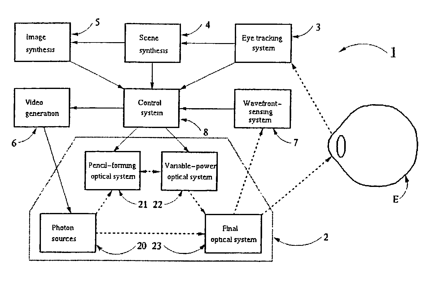
[0036] Referring to FIG. 1 a display device 1 comprises the following data processing components and an optical system 2:

[0037] an eye tracking system 3,

[0038] a scene synthesis system 4,

[0039] an image synthesis system 5,

[0040] a video generation system 6, and

[0041] a wavefront sensing system 7.

[0042] These interface with a control system 8, which in turn interfaces with components of the optical system 2 comprising:

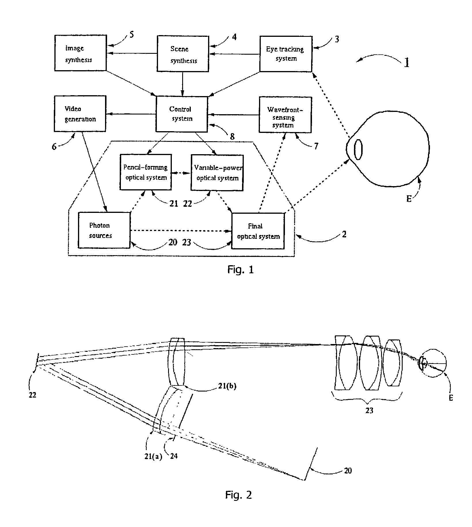
[0043] a photon source 20, having multiple pixels in a 2D surface,

[0044] an intermediate optical system, in this embodiment a pencil-forming system 21 which forms the photons into pencils, each pencil having photons from a single pixel, and

[0045] a variable power optical system 22 towards which pencils converge, and

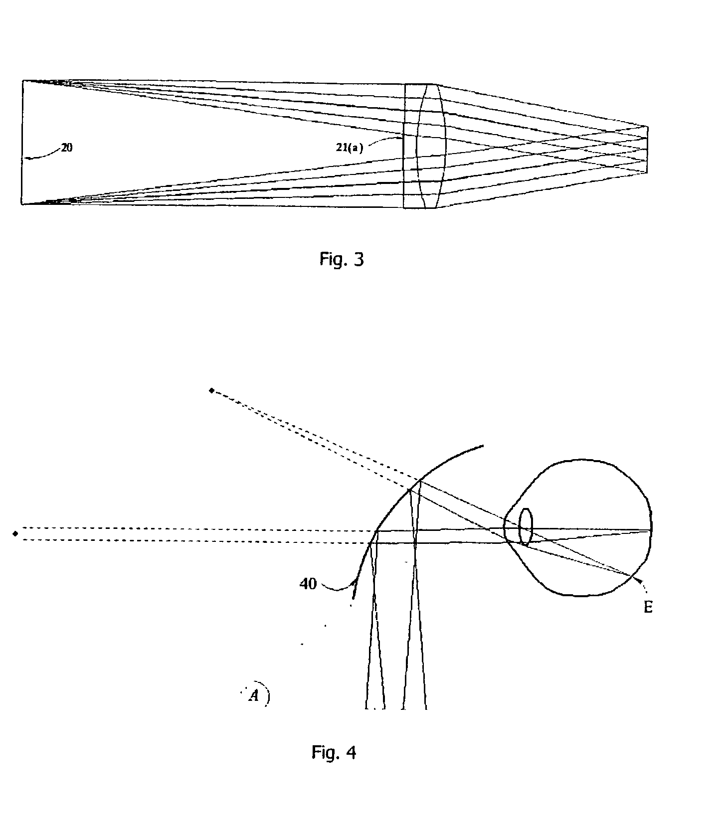
[0046] a final optical system 23 for directing photons into a user's eye E for viewing the source image.

[0047] The photon source 20 comprises a conventional cathode-ray tube. The pixels emit photons in near-spherical wavefronts when excited by an electron bea...


PUM


Abstract

A display device (1) has a photon source (20) that displays an image scene in which the user perceives points at differents distances, resulting in optical stimulation of the eye's accommodative response. This is achieved by an intermediate optical system (21) forming the photons into pencils and a variable power optical system (22) positioned for convergence of the pencils. A control system (8) controls the variable power optical system (22) to modulate photon wavefront curvature according to image pixel co-ordinate and intensity data and data representing required perceived pixel distance.

Description

[0001] The invention relates to a display device comprising:[0002] a photon source for emitting photons for a source image; the source comprising a plurality of pixels arranged in a surface;[0003] an intermediate optical system for direction of the emitted photons;[0004] a variable power optical system for modulating photon wavefront curvature from the intermediate optical system; and[0005] a final optical system for directing photons from the variable power optical system into a user's eye for viewing the source image with a perception of a changing image scene.PRIOR ART DISCUSSION[0006] PCT Patent Specification No. WO99 / 08145 (Isis Innovation) describes such a display device. Such display devices operate to present source images to a user's eyes so that the user has the perception of each source image pixel at any one of a continuum of distances. Applications of such a display device include investigation of the eye's accommodative response and stereoscopic image display without c...

Claims


Application Information

Patent Timeline
Patent Type & Authority Applications(United States)
IPC IPC(8): G02B26/08G02B27/22G02B27/01H04N13/00
CPCG02B27/0172G02B26/0825
Inventor SHEVLIN, FERGAL PATRICK
Owner SHEVLIN TECH
Why Eureka
Try Eureka