Tamper resistance device

Inactive Publication Date: 2002-10-24
HITACHI LTD
View PDF12 Cites 24 Cited by
  • Summary
  • Abstract
  • Description
  • Claims
  • Application Information

AI Technical Summary

Benefits of technology

0019] A technical problem to be solved by the present invention is how to lower the degree of relationship between data under processing and current consumption in a card member such as a chip for an IC card. If the degree of relationship between data under processing and current consumption in a chip for an IC card can be lowered, it will be difficult to infer the data under processing and a secret key in such a chip by observation of the waveform of current consumption. That is to say, the present invention provides high security to devices such as a card member.
0020] The present invention is focused on a technique to lower the degree of relationship between data under processing and current consumption in a card member such as a chip for an IC card. In accordance with this technique, data to be transformed is first transformed by using data for disturbance. The transformed data is then processed. Finally, a result of the processing is subjected to inverse transformation using the data for disturbance to obtain a correct processing result. In addition, the disturbance data used in transformation of data to be processed in order to lower the degree of relationship between data under processing and current consumption is generated in such a way that the probability of the hamming weight's always becoming a constant value, an all but constant value and a value indicating 0s or 1s in all bits of the data for disturbance in the binary expression of the data for disturbance is 0.5 or a value close to 0.5. Fur

Problems solved by technology

If the degree of relationship between data under processing and current consumption in a chip for an IC card can be lowered, it will be difficult to infer the data under processing and a secret key in such a chip by observation of the waveform of current consumption.
As a result, it is difficul

Method used


Image

  • Tamper resistance device
  • Tamper resistance device
  • Tamper resistance device

Examples


first embodiment

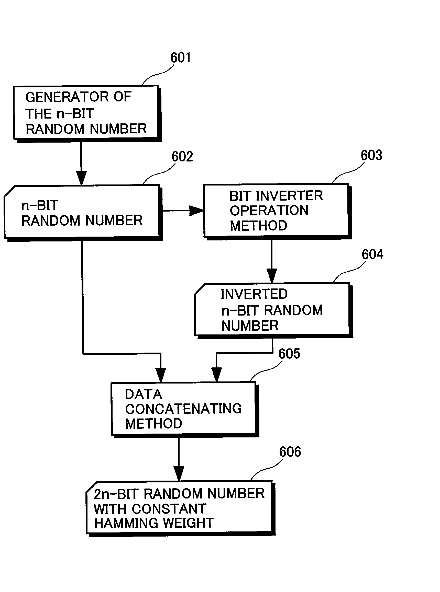
[0096] There are several techniques for generating random numbers having uniform and constant hamming weights. FIG. 6 is a diagram showing a data flow of a first embodiment implementing a technique to generate random numbers having constant uniform hamming weights. In this embodiment, the number of bits in a random number to be generated is 2n. As shown in the figure, first of all, an n-bit-random-number generator 601 generates an n-bit random number 602. The n-bit-random-number generator 601 may generate a pseudo random number or a true random number which is selected from results of measurement of a physical phenomenon. Then, a bit-inverting operation method 603 is used for inverting the generated n-bit ransom number 602 to produce an inverted n-bit ransom number 604. Subsequently, a data concatenation method 605 is used for concatenating the n-bit random number 602 and the inverted n-bit random number 604 to generate a constant-hamming-weight 2n-bit random number 606. This is bec...

second embodiment

[0098] FIG. 7 is a flowchart representing a second embodiment implementing a technique to generate random numbers having constant uniform hamming weights. As shown in the figure, the random-number generation represented by the flowchart begins with a step 702 at which a target hamming weight H is input. Then, at the next step 703, a random number R is generated. Subsequently, at the next step 704, the hamming weight RH of the generated random number R is computed. The flow of the random-number generation then goes on to a step 705 to form a judgment as to whether or not the hamming weight RH of the generated random number R is equal to the target hamming weight H. If the hamming weight RH of the generated random number R is not equal to the target hamming weight H, the flow of the random-number generation goes back to the step 703 at which another random number R is generated. If the hamming weight RH of the generated random number R is equal to the target hamming weight H, on the o...

third embodiment

[0099] FIG. 10 is a flowchart representing a third embodiment implementing a technique to generate random numbers having constant uniform hamming weights. First of all, pieces of m-bit data having uniform constant hamming weights are collected in a table. The embodiment generates only random numbers that have uniform constant hamming weights and each have a bit count equal to a multiple of m. As shown in the figure, the random-number generation represented by the flowchart begins with a step 1002 at which the bit count of a random number to be generated is set at n. Then, at the next step 1003, a result of division of n by m is substituted for L. In the basic flow of the random-number generation, L m-bit random numbers having uniform constant hamming weights are generated and concatenated to generate an n-bit random number having a constant hamming weight. Subsequently, at the next step 1004, a variable D for accommodating the n-bit random number being generated to have a constant h...


PUM


Abstract

It is an object of the disclosed technology to provide a tamper resistance device such as a card member having high security. The disclosed technology provides a solution to problems by reduction of the degree of relationship between information processed in the card member such as a chip for an IC card and current consumption for the processing. As a means for solving the problem, there is provided a method for reducing the degree of relationship between the magnitude of a current consumed by the chip for an IC card and information processed by the chip. In accordance with this method, information is transformed by using data for disturbance of the information prior to processing and, after the processing of the transformed data, the processed transformed information is subjected to inverse transformation using the data for disturbance of the information to result in correct processed information. The method is characterized in that the hamming weight of the data for disturbance of information is all but constant.

Description

2. BACKGROUND OF THE INVENTION[0001] The present invention relates to an information-processing apparatus and, more particularly, a tamper resistance device for highly confidential IC cards.[0002] An IC card is a device for holding personal information that must not be rewritten as one pleases, for encryption of data using a secret key treated as secret information and for decoding an encrypted text using the secret key. The IC card itself does not have a power supply. When the IC card is inserted into a reader and writer for the IC card, however, the IC card receives power from a power supply and becomes capable of carrying out operations. If the IC card is put in a state of being capable of carrying out operations, the IC card receives a command issued by the reader and writer and carries processing such as a transfer of data.[0003] The basic concept of the IC card 101 is shown in FIG. 1. As shown in the figure, a IC-card chip 102 is mounted on the IC card 101. In general, the IC ...

Claims


Application Information

Patent Timeline
IPC IPC(8): G06K19/07G06K19/073G07F7/10G09C1/00H04L9/06H04L9/10
CPCG06Q20/341G07F7/082H04L9/0625H04L2209/127H04L9/003G07F7/1008
Inventor ENDO, TAKASHIKAMINAGA, MASAHIROWATANABE, TAKASHIOHKI, MASARU
Owner HITACHI LTD
Why Eureka
Try Eureka