Supercharge Your Innovation With Domain-Expert AI Agents!

Method for conducting a leak test of a tank ventilation system of a vehicle

a technology for venting systems and tanks, applied in fluid tightness measurement, machines/engines, instruments, etc., can solve problems such as untight tank systems, additional circuit complexity, electrical lines, etc., and achieve the effect of reducing the cost of inspection, not only requiring technical complexity, but also a disadvantageous cos

Inactive Publication Date: 2002-10-31
ROBERT BOSCH GMBH
View PDF3 Cites 4 Cited by
  • Summary
  • Abstract
  • Description
  • Claims
  • Application Information

AI Technical Summary

Benefits of technology

[0007] This task is solved in a method for checking the operability of a tank-venting system of the kind described initially herein in accordance with the invention by the features of the independent claims 1 and 2.[0008] The basic idea of the invention is to draw a conclusion during tightness checks based on the time-dependent trace of the operating variable. For this purpose, the time-dependent trace of the operating variable is detected during the tank measurement and a conclusion is drawn as to the operability of the tank-venting valve from this time-dependent trace. A significant advantage of this method is that no additional lines, circuits, or the like are required in order to check the operability of the tank-venting valve. Rather, the time-dependent trace of the operating variable is evaluated during the tank measurement for checking the operability of the tank-venting valve which anyway takes place.[0009] A comparison to a reference measurement can take place as well as a comparison to a threshold which from operating variables for controlling an internal combustion engine of the vehicle or is fixedly pregiven.[0010] An advantageous embodiment of the method provides opening the tank-venting valve after the end of a tank measurement; detecting the time-dependent trace of the operating variable; and, drawing a conclusion as to the operability of the tank-venting valve when the operating characteristic variable drops by a pregiven value within a pregiven time. In this embodiment, a check can be made in a simple manner as to whether the tank-venting valve is jammed in the closed state. In this case, no leak would be detected but nonetheless a proper functioning of the tank-venting system would not be ensured.[0011] In another embodiment wherein the tightness of the tank-venting valve is checked, it is provided that the time-dependent trace of the operating characteristic variable is detected during a tank measurement executed during idle of the internal combustion engine of the vehicle (idle measurement). Then, the time-dependent trace of the operating variable is detected in a tank measurement carried out for a switched off internal combustion engine of the vehicle (run-on measurement) and a conclusion is drawn as to a disturbance of the tank-venting valve when the time-dependent gradient of the operating characteristic variable for the idle measurement departs from the comparable time-dependent gradient of the operating characteristic variable during the run-on measurement by a pregiven value. In this way, a check of the tightness of the tank-venting valve is possible in the closed state. In this way, especially a very fine leak in the tank-venting can be distinguished from a very fine leak at another location in the tank-venting system.[0012] As mentioned above, one or more of the following variables can be used as operating characteristic variables: the current take-up by the pressure source and / or the rpm of the pressure source and / or the voltage applied to the pressure source and / or the pressure generated by the pressure source.[0013] Insofar as a reference leak is used, it is preferably switched in parallel to the tank-venting system.

Problems solved by technology

For example, a tank-venting valve (jammed in the open position), which is disturbed in its operation, can lead to an untight tank system.
Operational checks of the tank-venting valve of this kind require additional electrical lines and additional circuit complexity.
These operational checks therefore not only require a technical complexity but especially also a disadvantageous cost.

Method used


Image

  • Method for conducting a leak test of a tank ventilation system of a vehicle
  • Method for conducting a leak test of a tank ventilation system of a vehicle
  • Method for conducting a leak test of a tank ventilation system of a vehicle

Examples


Embodiment Construction

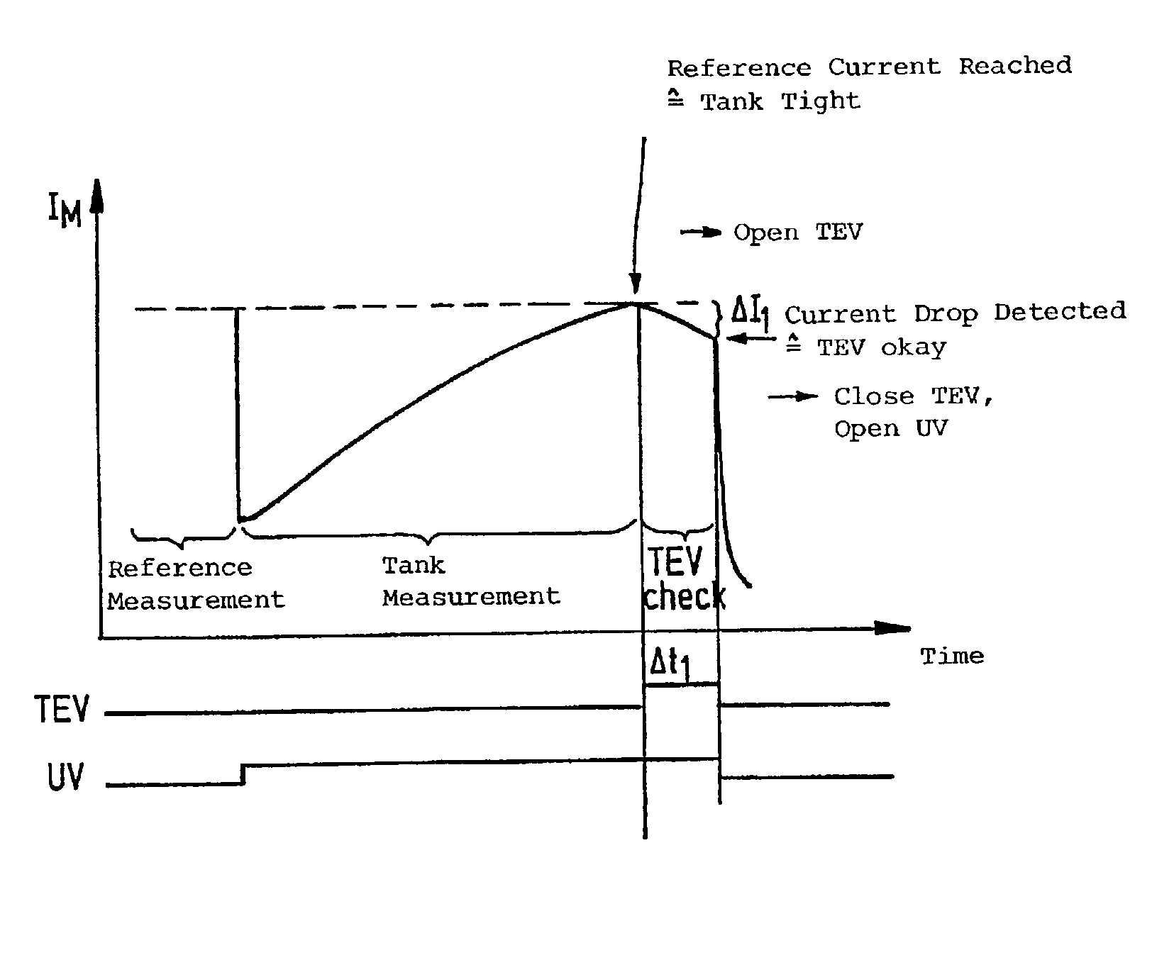
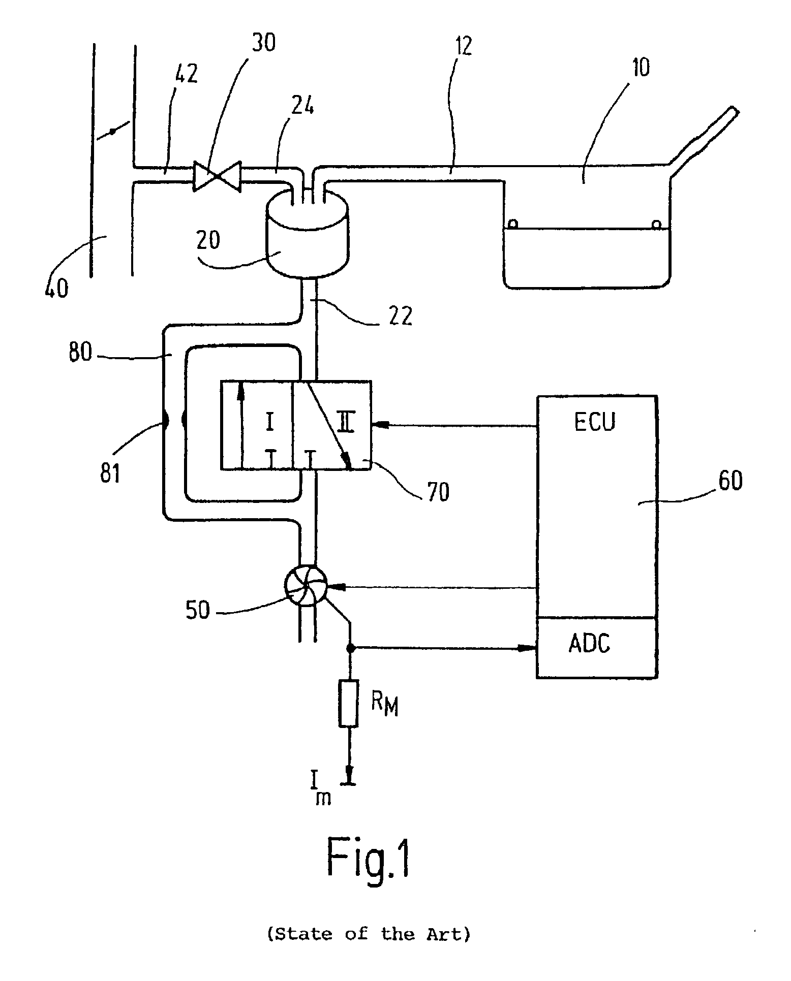
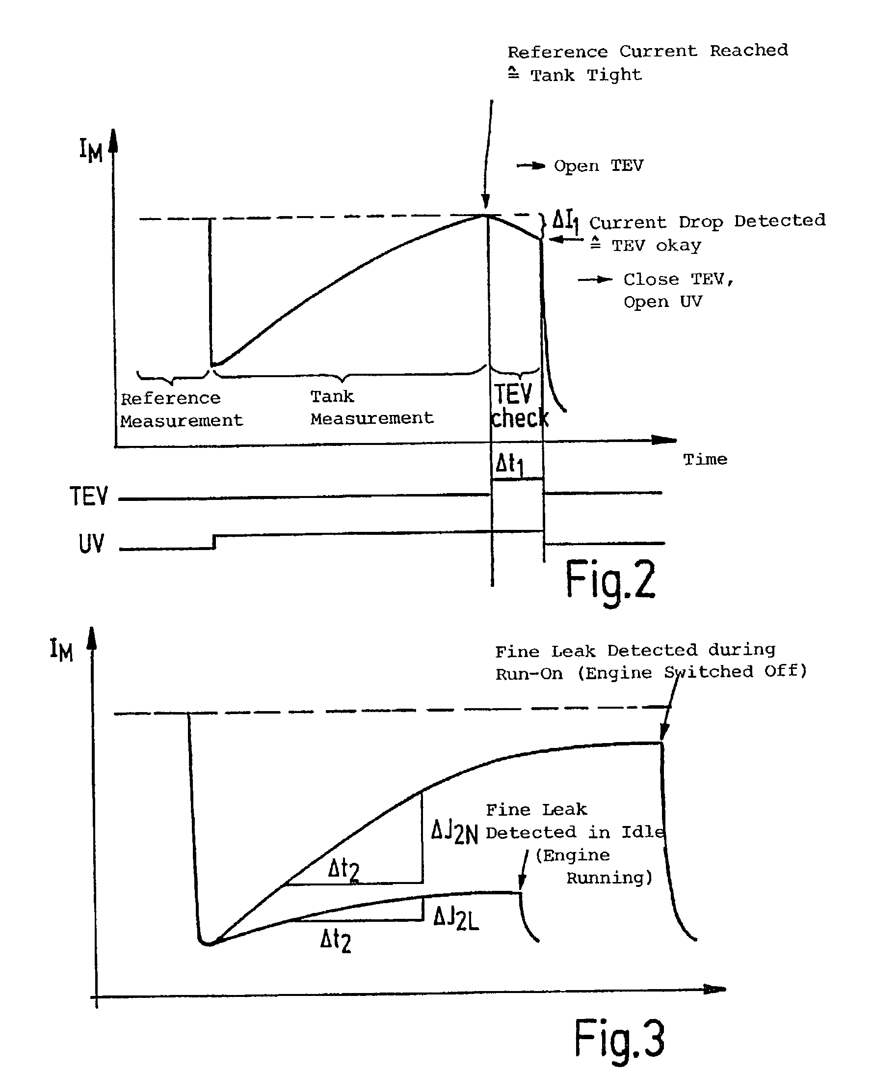
[0019] A tank-venting system of a motor vehicle, which is known from the state of the art, is shown in FIG. 1 and includes a tank 10, an adsorption filter 20 as well as a tank-venting valve 30. The adsorption filter 20 is, for example, an active charcoal filter which is connected to the tank 10 via a tank connecting line 12 and has a venting line 22 which can be connected to the ambient. The tank-venting valve 30 is, on the one hand, connected to the adsorption filter 20 via a valve line 24 and, on the other hand, is connected to an intake manifold 40 of an internal combustion engine (not shown) via a valve line 42.

[0020] Hydrocarbons develop in the tank 10 because of vaporization and these hydrocarbons deposit in the adsorption filter 20. For regenerating the adsorption filter 20, the tank-venting valve 30 is opened so that air of the atmosphere is drawn by suction through the adsorption filter 20 because of the underpressure present in the intake manifold 40 whereby the hydrocarbo...


PUM


Abstract

A method for checking the tightness of a tank-venting system of a vehicle wherein one introduces an overpressure or underpressure compared to the atmospheric pressure via a pressure source alternately into the tank-venting system and a reference leak of a defined size connected in parallel to the tank-venting system over a pregiven time interval and wherein one detects at least one operating characteristic variable of the pressure source when introducing the pressure into the tank-venting system (tank measurement) as well as when introducing the pressure into the reference leak (reference measurement) and wherein one compares the two measurements and, when there is a deviation of the tank measurement from the reference measurement by a pregivable value, one draws a conclusion as to a leak when there is a deviation of the tank measurement from the reference measurement by a pregivable value and the method is characterized in that one draws a conclusion as to the operability of the tank-venting valve of the tank-venting system from the time-dependent trace of the operating characteristic variable for the tank measurement.

Description

STATE OF THE ART[0001] The invention relates to a method for checking the tightness of a tank-venting system of a vehicle.[0002] Methods for checking tightness are shown, for example, in German patent publications 196 36 431 or from 198 09 384.[0003] In these methods, air is pumped into the tank-venting system with a pressure source. In this way, a pressure builds up in a tight tank-venting system. The increased pressure changes the operating characteristic variable of the pressure source, that is, for example, the electrical current requirement of the pump of the pressure source is increased. The measurement of the pump current thereby defines an index for the pressure in the tank. The pump current is measured at the start of the pumping operation and after the elapse of a pregiven time interval. An increase of the current is expected in a tight tank-venting system because of the pressure which builds up therein. A fault announcement "leakage" is outputted when the current increase...

Claims


Application Information

Patent Timeline
Patent Type & Authority Applications(United States)
IPC IPC(8): F02M25/08F02M37/00
CPCF02M25/0818
Inventor FRITZ, THORSTENREUSCHENBACH, LUTZ
Owner ROBERT BOSCH GMBH
Features
  • R&D
  • Intellectual Property
  • Life Sciences
  • Materials
  • Tech Scout
  • Unparalleled Data Quality
  • Higher Quality Content
  • 60% Fewer Hallucinations
Learn More