Fuel supply system

a technology of fuel supply system and fuel pressure, which is applied in the direction of electric control, positive displacement liquid engine, machine/engine, etc., can solve the problems of high processing speed of such data, increased controller load, and difficulty in detecting the precise speed of changing fuel pressure of the controller

Inactive Publication Date: 2002-10-31
HITACHI LTD
View PDF0 Cites 22 Cited by
  • Summary
  • Abstract
  • Description
  • Claims
  • Application Information

AI Technical Summary

Problems solved by technology

This increases the load on the controller.
Therefore, it is difficult for the controller to precisely detect a quickly-changing fuel pressure.
Further, it ...

Method used


Image

  • Fuel supply system
  • Fuel supply system
  • Fuel supply system

Examples


Embodiment Construction

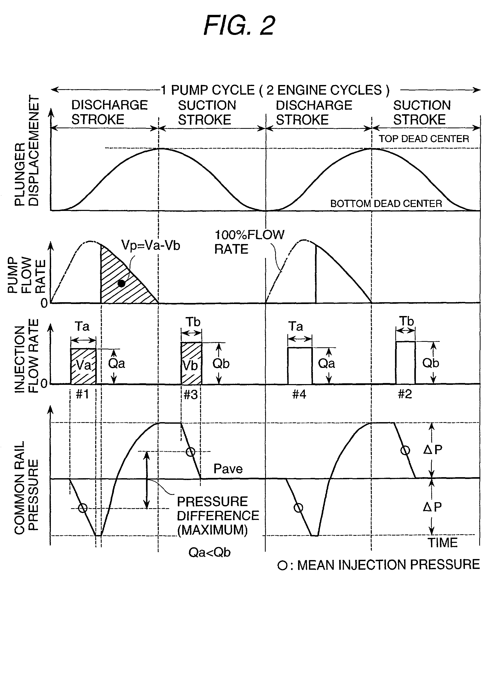
[0023] The object of the present invention is to provide a fuel supply system comprising a variable-volume single plunger pump which can make a single discharge while injectors for two cylinders inject fuel and a controller which controls the variable volume of the pump to keep the fuel supply pressure approximately constant.

[0024] Usually the single plunger pump intermittently takes in and out fuel. This causes the discharge pressure to pulsate greatly and makes uneven injection rates of the injectors. The present invention can solve this problem and makes the most of features of the pump such as low cost and energy saving.

[0025] The embodiments of the present invention will be explained in connection with the accompanying drawings.

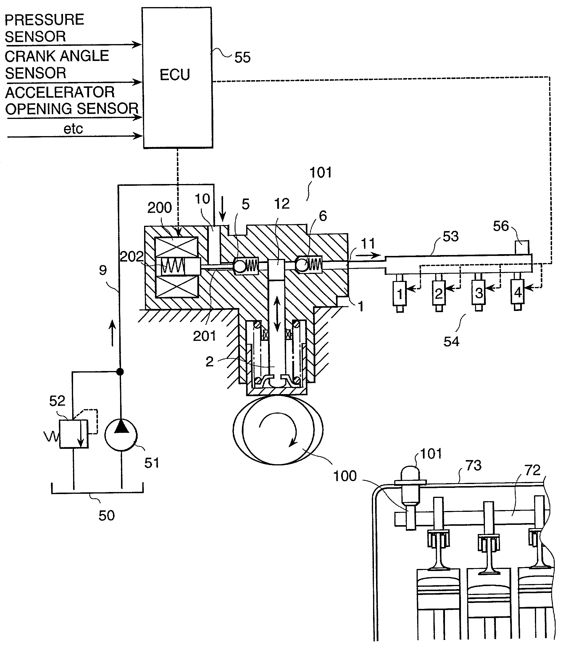
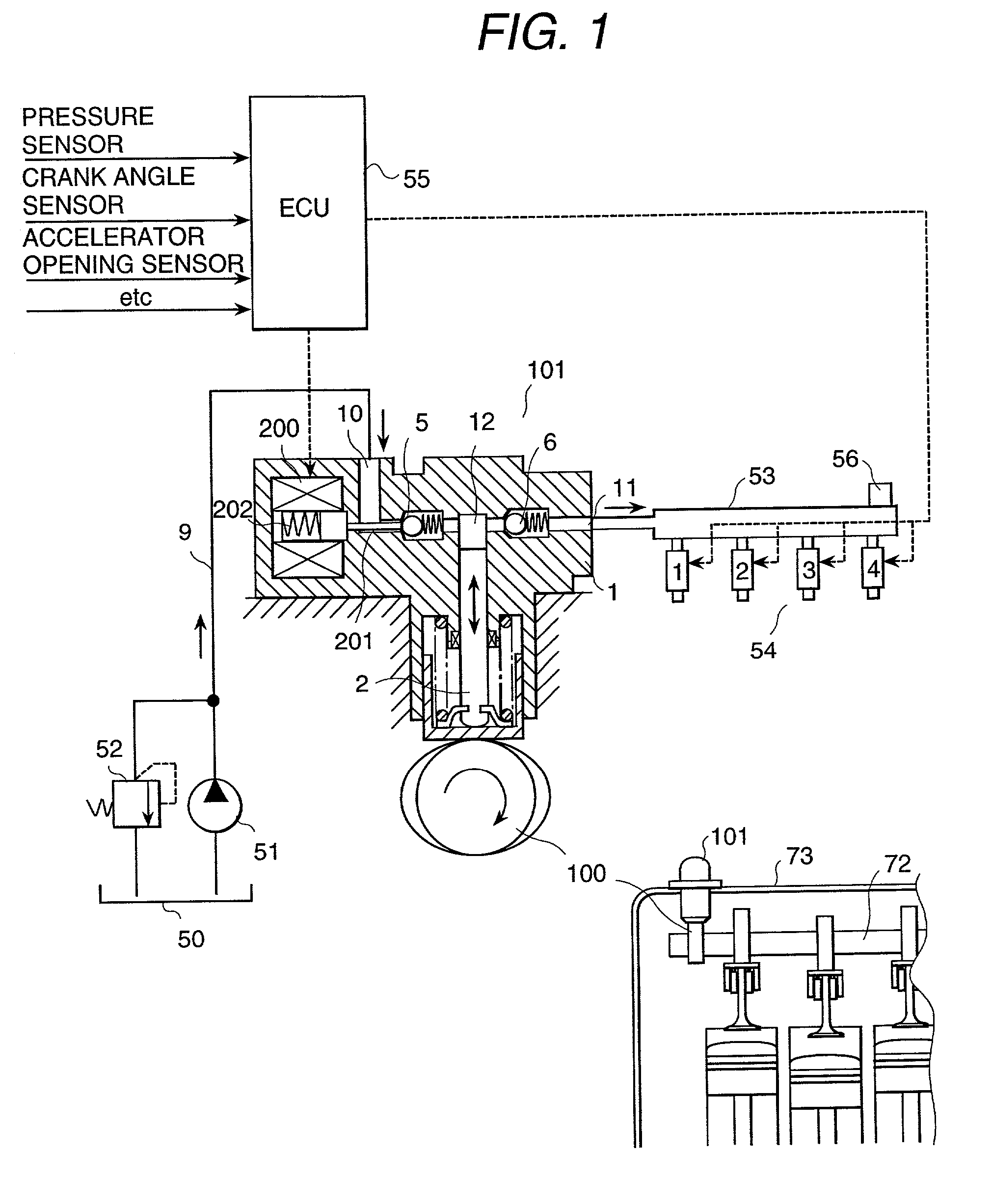
[0026] FIG. 1 is a schematic diagram of a fuel supply system which is an embodiment of the present invention, showing the details of a variable-displacement single plunger pump uses as a high-pressure fuel pump.

[0027] Referring to FIG. 1, the part 101 is...


PUM


Abstract

The present invention reduces the unevenness of injection rates of cylinders in a fuel supply system of a direct injection engine which uses a variable-displacement single plunger pump. The unevenness of injection rates of cylinders can be reduced by constructing so that the cam 100 which drives the high-pressure fuel pump 101 may make one reciprocation while the engine makes explosions by two cylinders and causing the controller 55 to extend the injection time width of one of two injectors 54 which inject while one discharge of the high-pressure fuel pump and to shorten the injection time width of the other injector.

Description

[0001] 1. Field of the Invention[0002] This invention relates to a fuel supply system for a direct injection engine.[0003] 2. Prior Art[0004] Fuel supply systems have been disclosed in the prior art. For example, Japanese Application Patent Laid-open Publication No. Hei 11-294243 discloses a system for detecting ever-changing fuel pressures with sensors, calculating an actual fuel injection rate of each fuel injection valve (hereinafter called an injector) from data sent from the sensors, correcting the fuel injection command value of each injector so as to match the actual fuel injection rate with a target fuel injection rate, and thus evening off the fuel injection rates of the cylinders.[0005] Further, Japanese Application Patent Laid-open Publication No. Hei 11-36935 discloses a system for obtaining a target fuel injection rate by extending the fuel injection time of an injector when the actual fuel pressure is lower than a target fuel pressure and shortening the fuel injection ...

Claims


Application Information

Patent Timeline
IPC IPC(8): F02M37/06F02D41/20F02D41/38F02D41/40F02M59/02F02M59/36F02M63/02F04B49/24
CPCF02D41/3809F02D41/3836F02D41/40Y02T10/44F02M63/0225F04B49/243F02M59/366Y02T10/40
Inventor HIRAKU, KENJITOKUO, KENICHIRONOGAMI, TADAHIKOTAKAO, KUNIHIKOYAMADA, HIROYUKI
Owner HITACHI LTD
Why Eureka
Try Eureka