Fuel vapor handling apparatus and diagnostic apparatus thereof

a technology of a diagnostic device and a fuel vapor handling device, which is applied in the direction of combustion-air/fuel-air treatment, machines/engines, and separation processes, etc., and can solve the problems of affecting the operation of the purge pump, the pressure increasing rate becomes less than the normal rate, and the practicality of the 30185

Inactive Publication Date: 2002-11-07
TOYOTA JIDOSHA KK +1
View PDF0 Cites 129 Cited by
  • Summary
  • Abstract
  • Description
  • Claims
  • Application Information

AI Technical Summary

Benefits of technology

[0011] Due to the intermittent operation, the canister internal temperature, which is reduced by the latent heat of vaporization at the time of desorption of fuel during an operating period, rises due to heat transferred from a canister-installed atmosphere and the like during a non-operating period between operating periods. Thus, desorption of fuel is facilitated. Therefore, fuel can be purged efficiently. Furthermore, corresponding to the amount of non-operating periods, the actual operating time of the purge pump is reduced, and the life of the purge pump increases. Practicality thus improves.
[0069] Therefore, if the engine temperature increases after a stoppage of the engine, the purge pump is reversely operated. For example, if the engine temperature at a stoppage of the engine is low, the fuel remaining in the intake port mostly remains in the intake port without vaporizing. Therefore, operation the purge pump during the stoppage of the engine will not eliminate fuel remaining in the intake port. However, if the engine temperature (intake port temperature) becomes higher than the temperature occurring at the time of the stoppage of the engine due to the effect of an air temperature rise, radiation heat of direct sunlight or the like, fuel remaining in the intake port during low temperatures may vaporize and fuel vapor may be discharged from the intake passage into the atmosphere. In the invention, in order to prevent discharge of fuel vapor due to a rise in engine temperature, the purge pump is operated in accordance with an engine temperature rise above the temperature occurring at the time of the stoppage of the engine, if there is any temperature rise. The aforementioned "the purge pump is operated in accordance with an engine temperature rise" includes not only starting operating the purge pump if the temperature rises by at least a certain amount, but also changing the operating duration of the pump in accordance with, for example, the size of increase in temperature, or operating the purge pump every time the engine temperature increases by a predetermined amount after the engine stops. In this aspect of the invention, since the purge pump is operated in accordance with an increase in the engine temperature after the stoppage of the engine, atmospheric discharge of fuel vapor can be reliably prevented even if the engine temperature at the time of a stoppage of the engine is low and fuel liquid remains in a relatively great amount in the intake port.

Problems solved by technology

However, the aforementioned technologies described in Japanese Patent Application Laid-Open Nos. 5-340315 and 11-30185 are not necessarily practical if accessory loss and the life spans of the purge pump and its power output section are taken into consideration.
However, if the purge pump is abnormal and its air ejecting capability drops, the pressure increasing rate becomes less the normal rate.
Therefore, if the operating time of the purge pump with the purge valve closed becomes longer than the upper limit time, it can be determined that the purge pump has an operation abnormality.
Therefore, if the engine temperature after a stoppage of the engine is high, the fuel vapor remaining in the intake passage vaporizes into fuel vapor within a relatively short time.
However, although fuel vapor is mainly produced near an intake port of the intake passage, the connecting portion (purge opening) between the intake passage and the purge passage is remote from the intake port.
Therefore, a delay time occurs before the fuel vapor produced near the intake port reaches the purge opening.
This delay time becomes short if the engine temperature is high and fuel vapor is rapidly produced in a great amount after a stoppage of the engine.
This delay time becomes relatively long if the engine temperature is low and the amount of fuel vapor produced is small.
Therefore, operation the purge pump during the stoppage of the engine will not eliminate fuel remaining in the intake port.
However, if the engine temperature (intake port temperature) becomes higher than the temperature occurring at the time of the stoppage of the engine due to the effect of an air temperature rise, radiation heat of direct sunlight or the like, fuel remaining in the intake port during low temperatures may vaporize and fuel vapor may be discharged from the intake passage into the atmosphere.

Method used


Image

  • Fuel vapor handling apparatus and diagnostic apparatus thereof
  • Fuel vapor handling apparatus and diagnostic apparatus thereof
  • Fuel vapor handling apparatus and diagnostic apparatus thereof

Examples


second embodiment

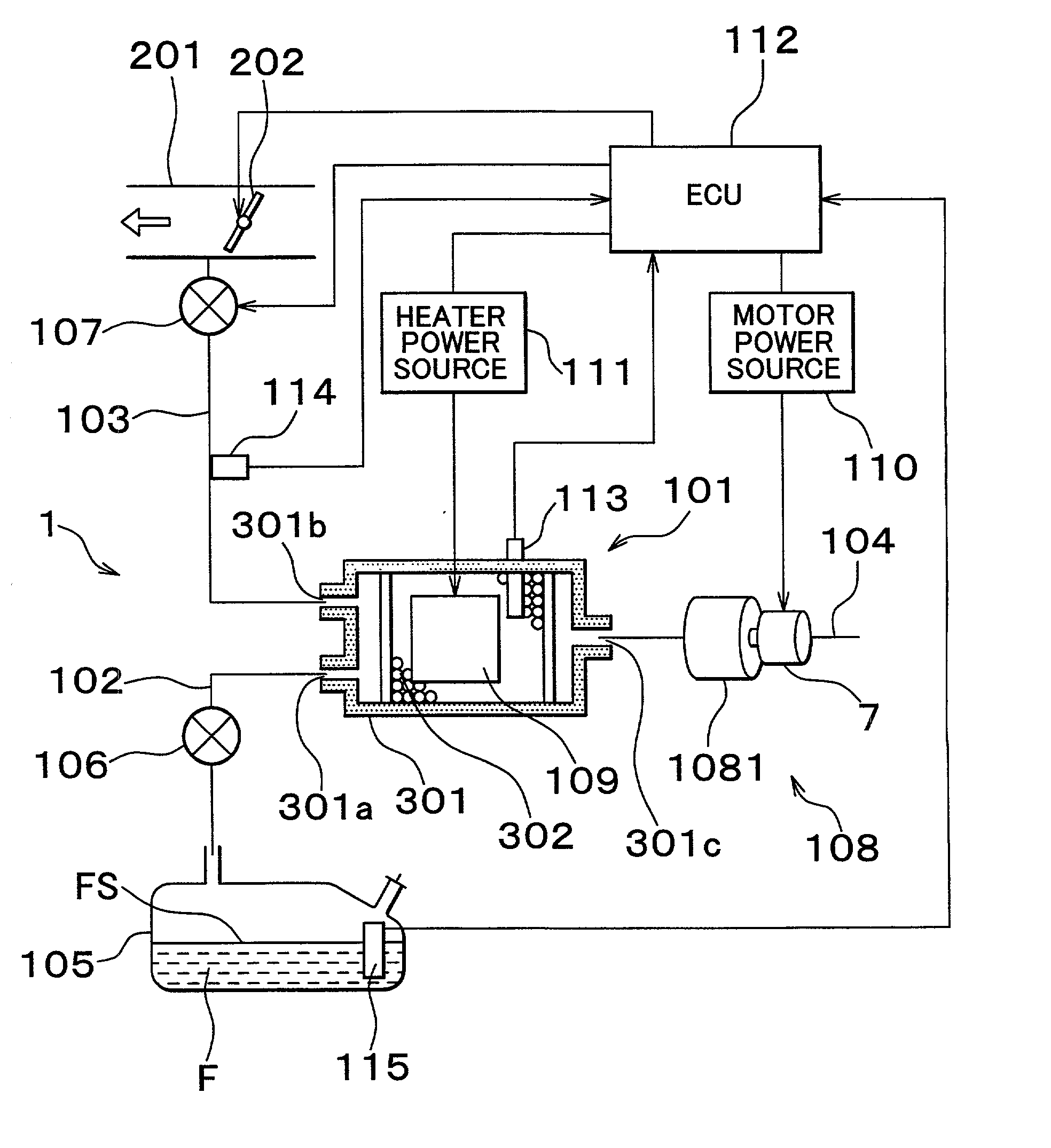
[0139] FIG. 8 shows a fuel vapor handling apparatus in accordance with a second embodiment of the invention. The construction of the second embodiment is basically the same as that of the first embodiment. Features distinguishing the second embodiment from the first embodiment will mainly be described below.

[0140] In a fuel vapor handling apparatus 1A of this embodiment, a pump valve 116 that serves as a metering valve is provided in an atmospheric passage 104 immediately downstream of a purge pump 108. The pump valve 116 is an electromagnetic valve designed so that the degree of opening of the valve is variable. The degree of opening of the valve is adjusted based on a control signal from an ECU 112A.

[0141] FIG. 9 indicates a relationship between the ejection pressure of the purge pump 108 and the amount of flow ejected therefrom determined while the degree of opening of the pump valve 116 is changed. As the degree of valve opening is decreased, the ejection pressure increases and ...

third embodiment

[0145] FIG. 10 shows a fuel vapor handling apparatus in accordance with a third embodiment of the invention. The construction of the third embodiment is basically the same as that of the first embodiment of the invention. Features distinguishing the third embodiment from the first embodiment will be mainly described below.

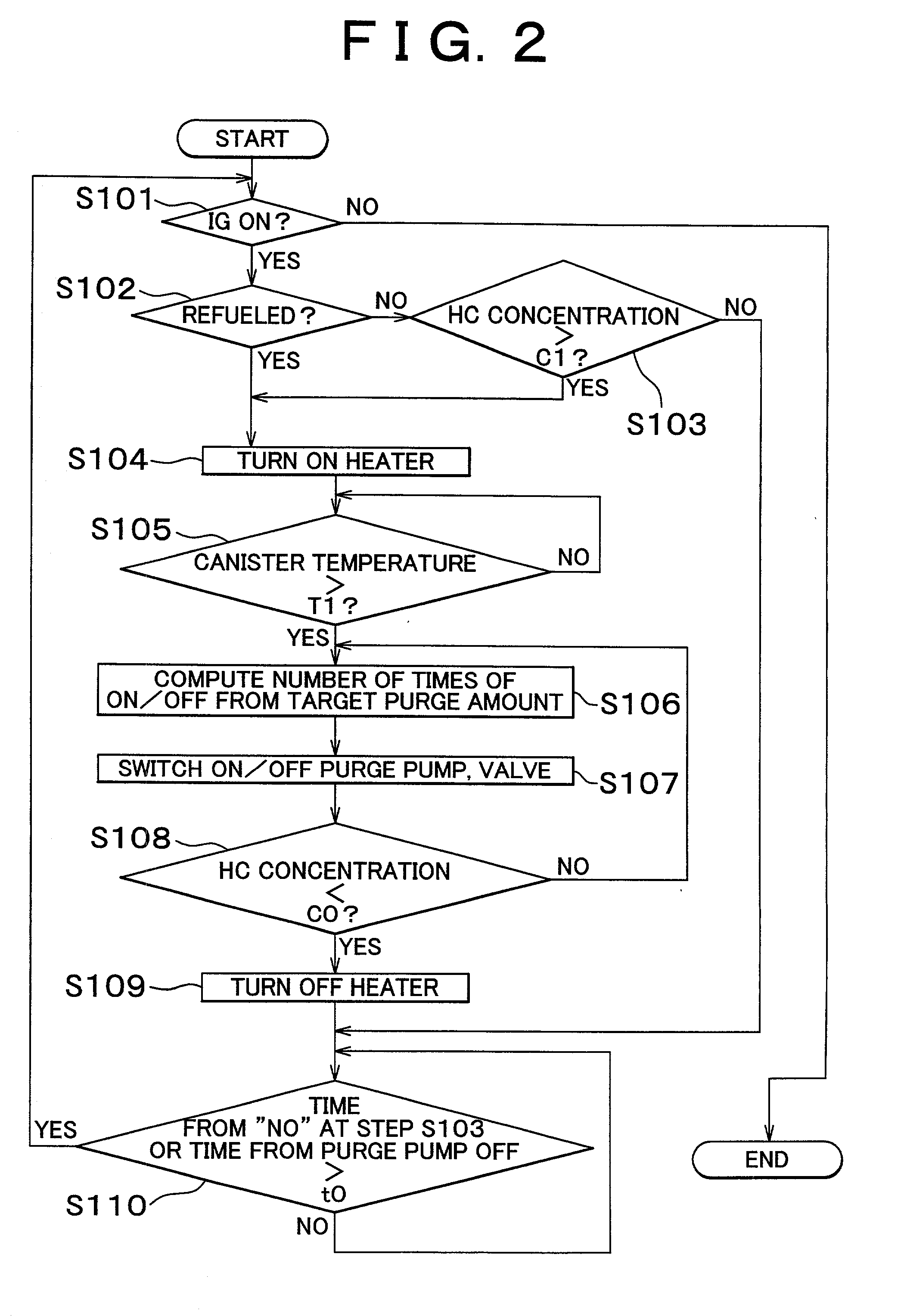
[0146] An ECU 112B of a fuel vapor handling apparatus 1 of this embodiment executes control programs different from those of the first embodiment. FIG. 11 shows a flow of a fuel vapor purge control executed by the ECU 112B. After the ignition switch is turned on (step S201), it is determined whether refueling is performed (step S202). If refueling is not performed, the process proceeds to step S203, in which an amount of purge flow that is uniquely determined by the degree of purge valve opening is input. Subsequently in step S204, the HC concentration determined by the HC concentration sensor 114 is input. Subsequently in step S205, an amount of purge fuel is comp...

fourth embodiment

[0160] FIG. 12 shows a fuel vapor handling apparatus in accordance with a fourth embodiment of the invention. The construction of the fourth embodiment is basically the same as that of the second embodiment of the invention. Features distinguishing the fourth embodiment from the second embodiment will be mainly described below.

[0161] In an fuel vapor handling apparatus 1C of this embodiment, a fuel tank 105 is provided with a pressure sensor 117 for detecting the pressure inside the fuel tank 105 (hereinafter, referred to as "tank internal pressure sensor"). A detection signal from the sensor is input to an ECU 112C. The ECU 112C executes control programs different from those of the second embodiment. FIG. 13 shows a flow of a fuel vapor purge control executed by the ECU 112C. After the ignition switch is turned on (step S301), it is determined whether the amount of fuel remaining in the fuel tank 105 is greater than or equal to a predetermined amount V0 based on a detection signal ...


PUM


Abstract

A fuel vapor handling apparatus supplies a purging air to a canister by using a purge pump and purges fuel desorbed from the canister into an intake pipe. A controller intermittently operates the purge so that the canister internal temperature recovers from a reduced level caused by the latent heat of vaporization of fuel during an operating period of the purge pump. Therefore, desorption of fuel from the canister during an operating period is facilitated. Since the actual operating time of the purge pump is reduced, the life of a motor that is a power unit of the purge pump becomes longer.

Description

INCORPORATION BY REFERENCE[0001] The disclosures of Japanese Patent Applications Nos. 2001-135026 filed on May 2, 2001 and 2001-226436 filed on Jul. 26, 2001, including their specifications, drawings and abstracts, are incorporated herein by reference in their entireties.[0002] 1. Field of Invention[0003] The invention relates to a fuel vapor handling apparatus of an internal combustion engine, and to a diagnostic apparatus of the fuel vapor handling apparatus.[0004] 2. Description of Related Art[0005] Internal combustion engines that use a high-volatile fuel, such as gasoline or the like, are equipped with a fuel vapor handling apparatus for preventing fuel vapor formed in a fuel tank from being released into the atmosphere. Fuel vapor handling apparatus equipped with a canister are widely known. A canister is formed by a container and a fuel adsorption-capable adsorbent contained in the container. Fuel vapor introduced from the fuel tank via a fuel vapor introducing port is tempor...

Claims


Application Information

Patent Timeline
Patent Type & Authority Applications(United States)
IPC IPC(8): B01D53/04F02M25/08
CPCF02M25/089F02M2025/0881F02M25/0872F02M25/0809F02M25/0818B01D53/0454
Inventor HYODO, YOSHIHIKOYOSHIOKA, MAMORUKAWANO, TAKANOBUITAKURA, HIDEAKITAKEYAMA, MASAKIKATO, NAOYA
Owner TOYOTA JIDOSHA KK
Why Eureka
Try Eureka