Battery mounting assembly

a battery mounting and assembly technology, applied in the direction of electric propulsion mounting, cell component details, cell components, etc., can solve the problems of undesirable interaction between people or the environment, battery mounting to the battery mounting assembly is relatively small risk

Inactive Publication Date: 2002-11-07
INT TRUCK INTPROP LLC
View PDF0 Cites 40 Cited by
  • Summary
  • Abstract
  • Description
  • Claims
  • Application Information

AI Technical Summary

Benefits of technology

[0003] It is thus, an object of the present invention to provide a battery mounting assembly to which a relatively large volume of batteries may be mounted within a relatively compact space. A further object of the present invention is to provide a battery mounting assembly, for which, the risk that the batteries mounted to the vehicle will interact with people or the environment in undesirable ways in the event that the vehicle is involved in a traffic accident is relatively low.
[0004] The battery mounting assembly of the present invention provides structure for supporting a number of batteries on a first layer and structure for supporting a plurality of batteries on a second layer spaced vertically above the first layer. By mounting a plurality of batteries on a first layer and a second layer that are spaced below and above one another respectively the battery mounting assembly provides for mounting of relatively large number of batteries within a space that is relatively compact longitudinally and laterally.
[0005] The battery mounting assembly is constructed such that there is a relatively small risk that the batteries that are mounted to the battery mounting assembly will interact in an undesirable manner with people or the environment in the event that the vehicle is involved in a traffic accident. At least one embodiment of the battery mounting assembly of the present invention performs in accordance with the safety standards set forth by the Society of Automotive Engineers document J1766. One embodiment of the battery mounting assembly of the present invention is constructed to deform and move in predetermined ways and thus absorb and dissipate large amounts of energy when the battery mounting assembly is subjected to forces and accelerations greater than those experienced during normal vehicle operation. Because the battery mounting assembly of the present invention deforms and moves in such predetermined directions when the vehicle is involved in traffic accidents the mounting of the batteries to the vehicle is maintained and the batteries remain relatively undamaged in all but the most severe traffic accidents. The battery mounting assembly of the present invention is carefully designed such that the strength of certain portions of the battery mounting assembly in certain directions is of a certain proportion of the strength of certain other portions of the battery mounting assembly in certain directions. This proportioning of the strengths of various portions of the battery mounting assembly to one another is what causes the battery mounting assembly to deform and move in predetermined directions when the battery mounting assembly is subjected to forces and accelerations greater than those of normal vehicle operation. The battery mounting assembly is also preferably constructed in a manner such that there is a relatively small risk of electrically conductive components contacting the electrical connections of the batteries as a result of deformations and motions of the vehicle as a result of the vehicle's involvement in a traffic accident. This reduces the risk that the electrical connections of the batteries will be short-circuited as a result of the vehicle's involvement in a traffic accident.

Problems solved by technology

The battery mounting assembly is constructed such that there is a relatively small risk that the batteries that are mounted to the battery mounting assembly will interact in an undesirable manner with people or the environment in the event that the vehicle is involved in a traffic accident.

Method used


Image

  • Battery mounting assembly
  • Battery mounting assembly
  • Battery mounting assembly

Examples


Embodiment Construction

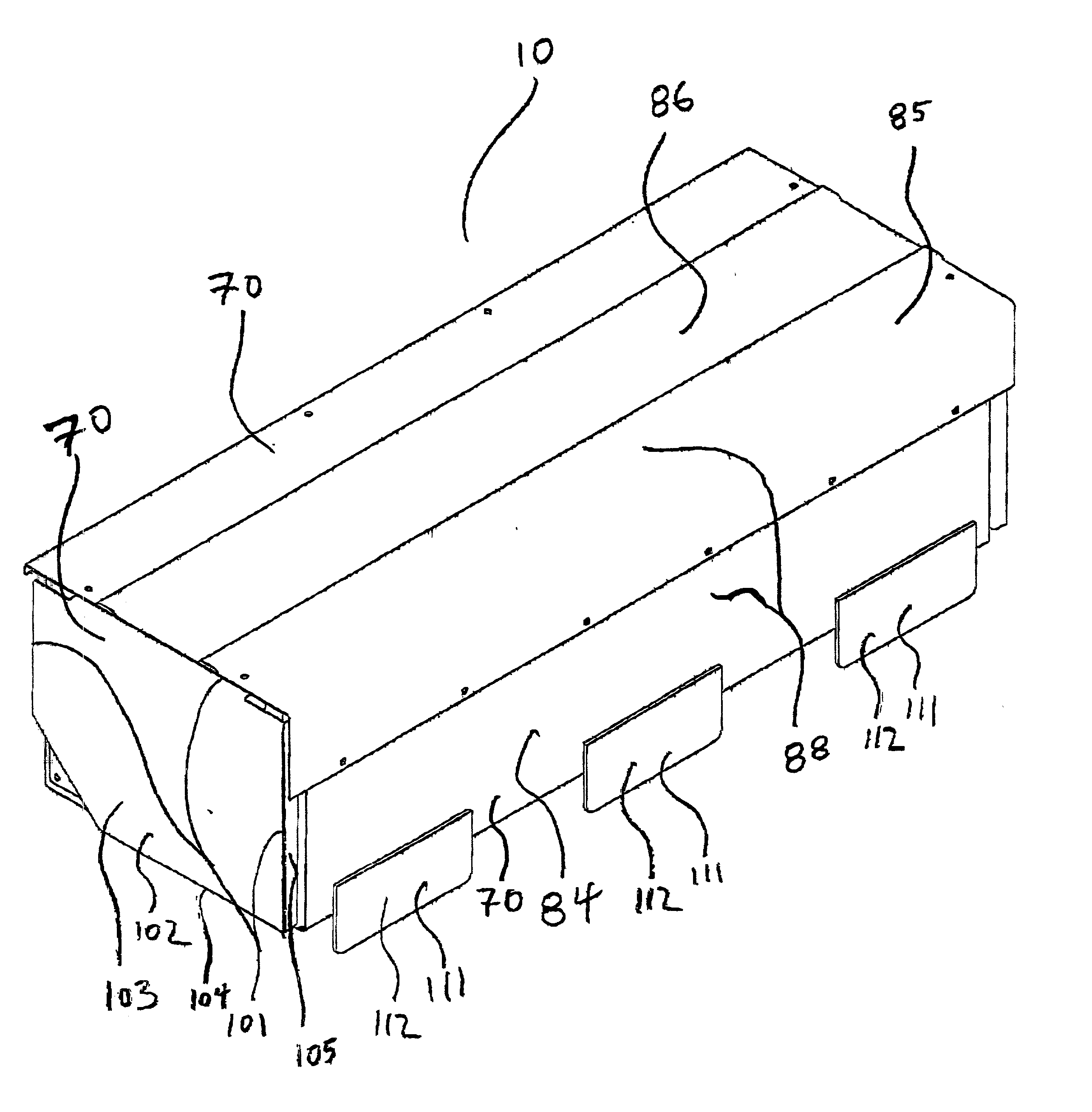
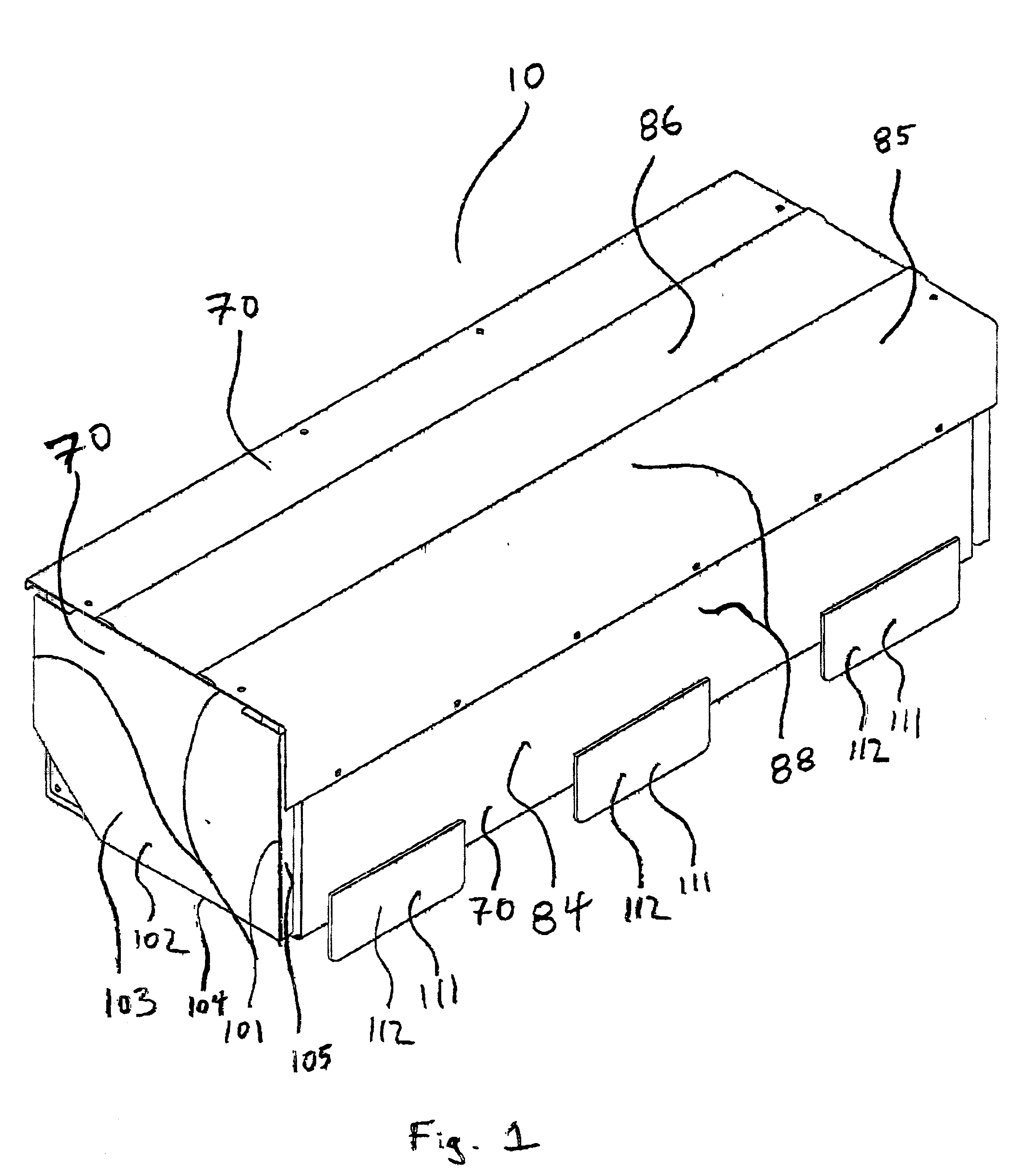
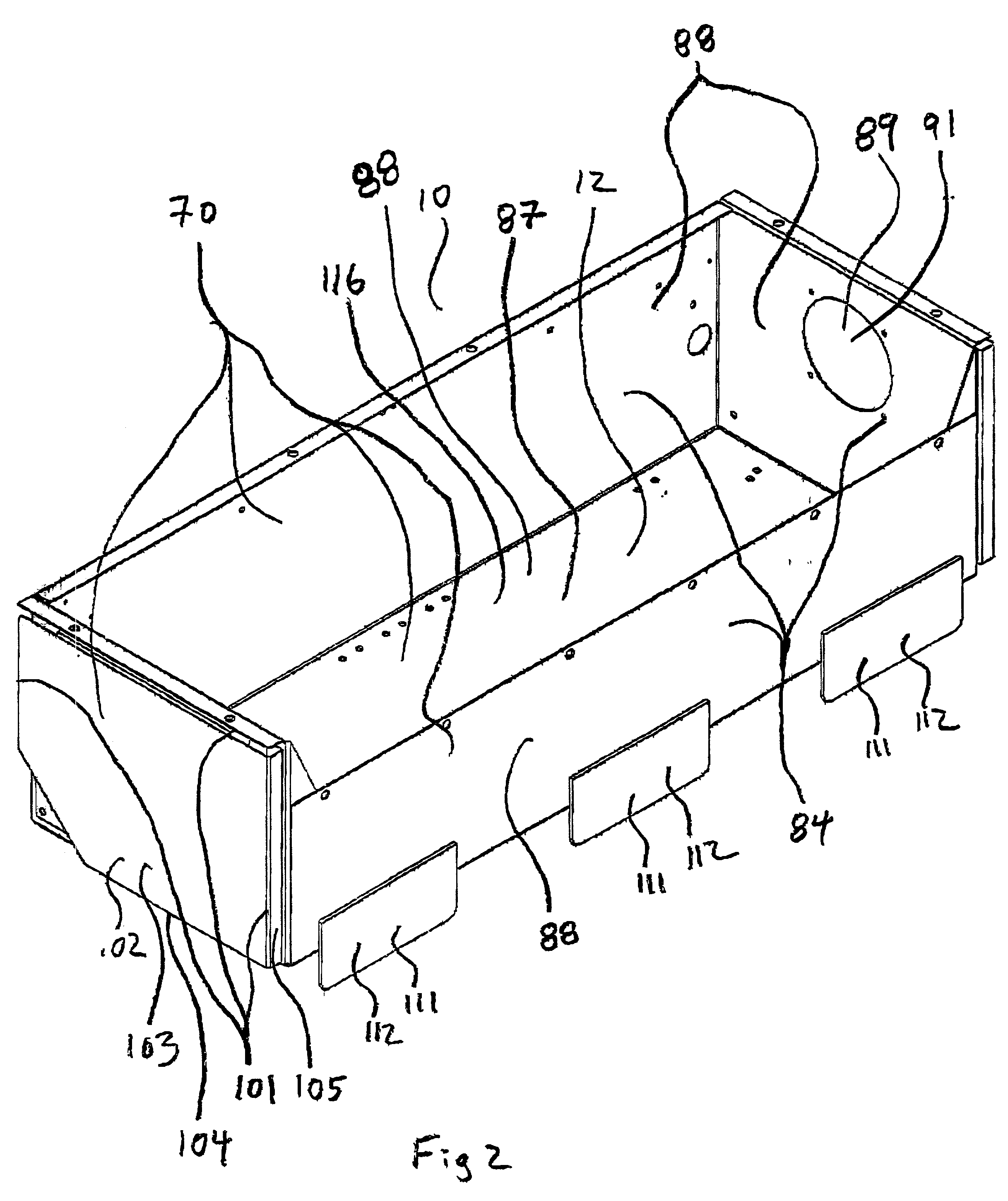
[0035] The present invention is a first battery mounting assembly 10 for mounting batteries 16 to a vehicle 15. The first battery mounting assembly 10 includes one or more main support members 11 that are directly or indirectly engaged to structural components 17 of the vehicle 15. A first lower battery tray 12, upon which a plurality of batteries 16 may be supported, is engaged to and supported by the one or more main support members 11.

[0036] The first battery mounting assembly 10 of the present invention preferably includes structure for mounting a plurality of batteries 16 above those batteries 16 that are supported by the first lower battery tray 12. One or more embodiments of battery mounting assemblies 10 and / or battery mounting assembly components that are constructed in a manner such that they effect such feature(s) are best illustrated in FIGS. 5, 8, 22, 23, 24, 25, 26, and 27. One or more upper tray support components 13 are directly or indirectly engaged to and supported...


PUM


Abstract

A battery mounting assembly for mounting batteries to a vehicle. The battery mounting assembly has lower battery tray and an upper battery tray disposed below and above one another respectively. The battery mounting assembly is constructed to move and deform in predetermined ways when it is subjected to relatively large forces such as might occur when the vehicle is involved in a traffic accident. The battery mounting assembly has one or more bumper components intended to protect batteries mounted to the battery mounting assembly from being subjected to a direct impact. Steel components of the battery mounting assembly are coated with an elastomer that has a high electrical resistance.

Description

[0001] The present invention relates to assemblies for mounting batteries to vehicles. Modern vehicles utilize electrochemical batteries (hereinafter referred to as batteries) to store relatively large amounts of electrical energy. Some vehicles such as electric vehicles and hybrid electric vehicles need to store especially large quantities of electrical energy. Often the amount of electrical energy that can be stored on such a vehicle is limited as a result of limited space on the vehicle for batteries. The electrical energy stored in the batteries of an electric or hybrid electric vehicle is utilized to provide a "power reserve" at times when the desired rate of travel of the vehicle requires more power than what is being generated by any electrical generators of the vehicle. Such a vehicle can only be propelled at speeds and accelerations that require the "power reserve" until the electrical energy stored in the batteries is depleted. Thus, the quantity of energy stored in the ba...

Claims


Application Information

Patent Timeline
Patent Type & Authority Applications(United States)
IPC IPC(8): B60K1/04H01M50/204H01M50/224H01M50/231H01M50/242H01M50/244H01M50/249H01M50/262H01M50/271
CPCB60K1/04H01M2/1094H01M2/1083H01M2/1077Y02E60/10H01M50/24H01M50/204H01M50/249H01M50/224H01M50/231H01M50/242H01M50/262H01M50/271H01M50/244
Inventor MAUS, JEREMY P.MINK, RICHARD A.SCHULER, NATHAN L.WEISSNER, STEVEN W.
Owner INT TRUCK INTPROP LLC
Why Eureka
Try Eureka