Active matrix substrate for liquid crystal display and its fabrication

Inactive Publication Date: 2002-11-28
VISTA PEAK VENTURES LLC
View PDF9 Cites 43 Cited by
  • Summary
  • Abstract
  • Description
  • Claims
  • Application Information

AI Technical Summary

Problems solved by technology

Deposition of a mask requires time and cost.
Heat treatment, such as baking or annealing, after forming the scanning and signal lines out of the material is unavoidable.
However, the pure aluminum has poor capacity to withstand heat, minute protrusions, called hillocks,

Method used


Image

  • Active matrix substrate for liquid crystal display and its fabrication
  • Active matrix substrate for liquid crystal display and its fabrication
  • Active matrix substrate for liquid crystal display and its fabrication

Examples


Embodiment Construction

[0053] Referring to the accompanying drawings, the same reference numerals are used to designate same or similar parts or portions throughout each view of Figures for the sake of brevity of description.

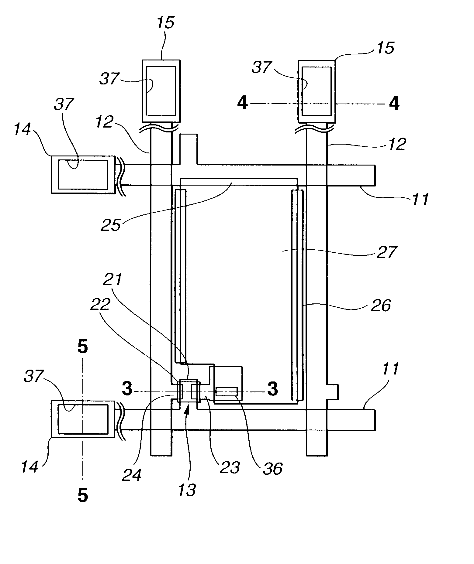
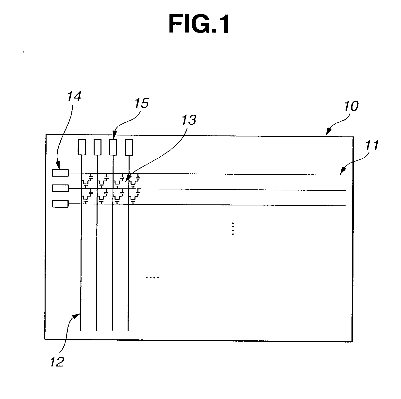
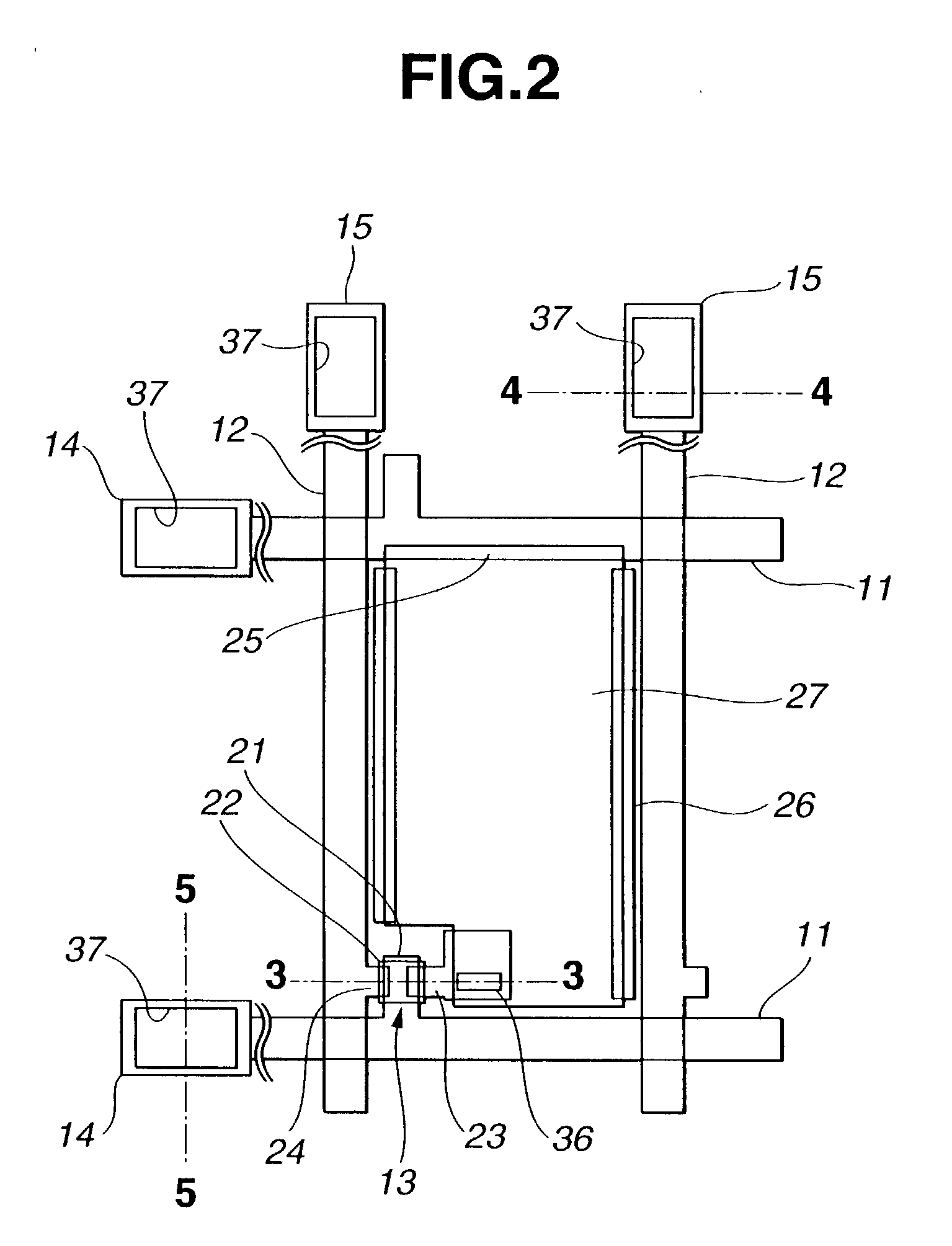
[0054] With reference to FIGS. 1 to 6, a first exemplary embodiment of an active matrix substrate 10 is described. FIG. 6 shows a liquid crystal display (LCD) incorporating the active matrix substrate 10. Referring also to FIG. 6, the LCD includes, in addition to the active matrix substrate 10, a color filter substrate 40, and liquid crystal 46 interposed between the two substrates 10 and 40. To prevent the liquid crystal 46 from leaking out of a display area of the LCD, a seal 45 is provided between the substrates 10 and 40. The active matrix substrate 10 includes a transparent substrate 31, a matrix array of thin film transistors (TFTs) 13 and pixel electrodes 27, which are disposed in the display area on the transparent substrate 31. The opposing color filter substrate 40 includes ...


PUM


Abstract

An active matrix substrate comprises a matrix array of TFTs. A double-layered film includes an under-layer of aluminum-neodymium (Al-Nd) alloy and an over-layer of high melting point metal. The double-layered film forms first interconnection lines for connection to the TFTs. A triple-layered film includes an under-layer of said high melting point metal, a middle-layer of said Al-Nd alloy and an over-layer of the high melting point metal. The triple-layered film forms second interconnection lines for connection to the TFTs.

Description

[0001] 1. Field of the Invention[0002] The present invention relates to an active matrix substrate for a liquid crystal display and a method of fabricating an active matrix substrate.[0003] 2. Description of the Related Art[0004] Active matrix substrates are widely used in liquid crystal displays and include interconnections. The interconnections include assemblies of scanning and signal lines. In order to create the interconnections, the fabrication of such active matrix substrates requires deposition of a mask each time upon application of photolithography and etching. Deposition of a mask requires time and cost. A need remains to minimize the number of steps of the mask deposition in a direction toward a cost and time reduction in fabricating an active matrix substrate. Various fabrication methods have been proposed, which use four or five masks. Examples of such fabrication methods using five masks are found in JP-A 9-171197 and JP-A 9-197433. An example using four masks is foun...

Claims


Application Information

Patent Timeline
IPC IPC(8): G02F1/1333G02F1/1343G02F1/1362G02F1/1368G09F9/00G09F9/30G09F9/35H01L21/28H01L21/306H01L21/3205H01L21/77H01L21/84H01L23/52H01L27/12H01L29/45H01L29/49H01L29/786
CPCG02F1/13458G02F1/136286G02F2001/13629H01L27/124H01L27/12H01L29/458H01L29/4908G02F2001/136295G02F1/13629G02F1/136295G02F1/1333
Inventor MAEDA, AKITOSHITANAKA, HIROAKIKIMURA, SHIGERUKIMURA, SATOSHI
Owner VISTA PEAK VENTURES LLC
Why Eureka
Try Eureka