Chemical mechanical processing system with mobile load cup

Inactive Publication Date: 2002-11-28
APPLIED MATERIALS INC
View PDF0 Cites 22 Cited by
  • Summary
  • Abstract
  • Description
  • Claims
  • Application Information

AI Technical Summary

Benefits of technology

0026] To facilitate understanding, identical reference numerals have been used,

Problems solved by technology

Thus, tools having small footprints and high production c

Method used


Image

  • Chemical mechanical processing system with mobile load cup
  • Chemical mechanical processing system with mobile load cup
  • Chemical mechanical processing system with mobile load cup

Examples


Example

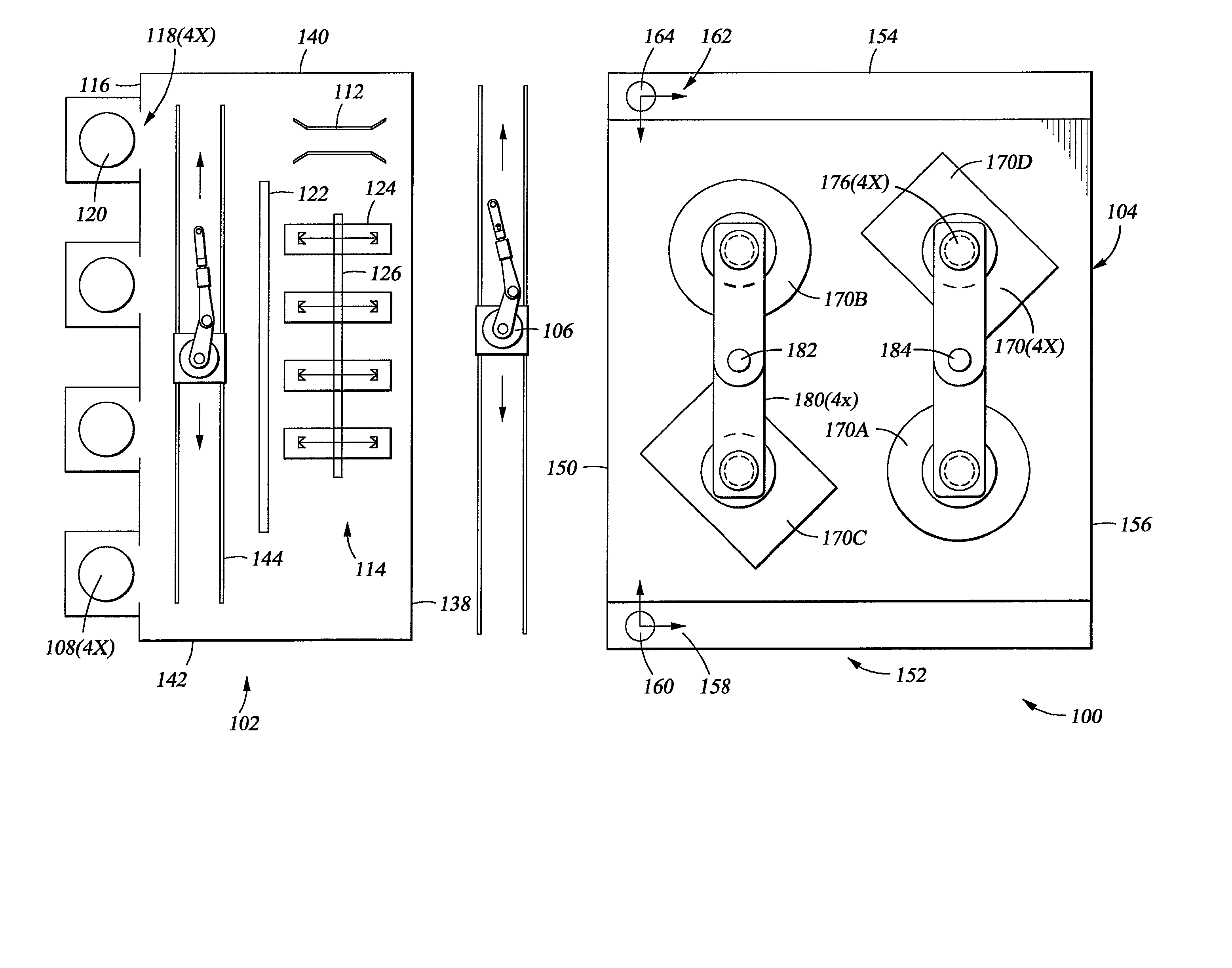
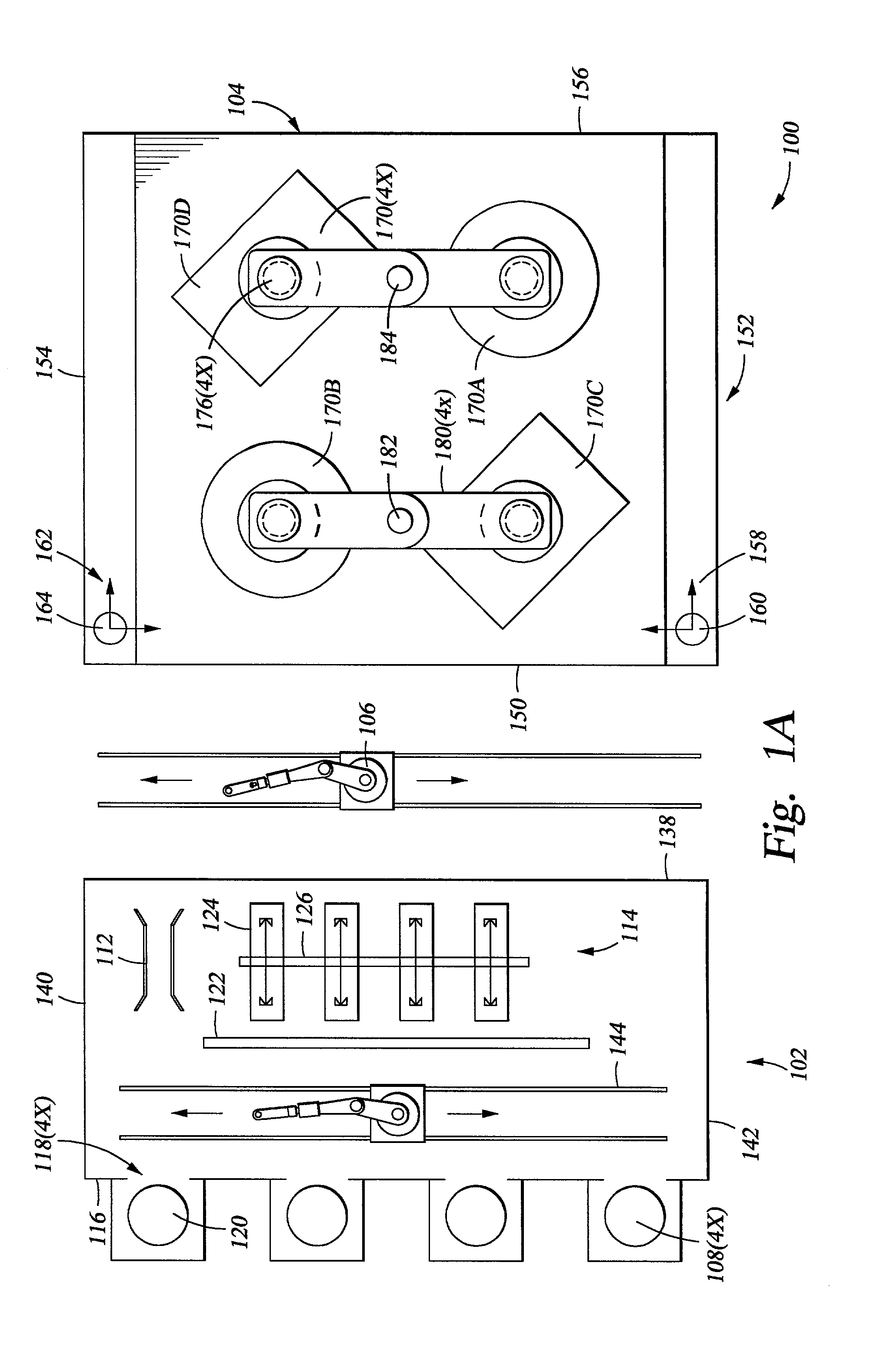
[0027] FIGS. 1A and 2 depict plan and side views of one embodiment of a chemical mechanical polishing system 100. Referring simultaneously to FIGS. 1A and 2, the system 100 generally includes a modular factory interface 102 and a polisher 104. Substrates 120 processed on the system 100 are passed between the factory interface 102 and the polisher 104 by a substrate handler 106 and a pair of movable load cups 160, 162.

[0028] The factory interface 102 and the polisher 104 each have an enclosure 208, 210, respectively, to minimize contamination of the substrates 120 processed therein. Typically, the substrate handler 106 is enclosed in a third enclosure 212 to maintain a clean environment through with substrates 120 are passed between the factory interface 102 and the polisher 104. Generally, the environment of the factory interface 102 is maintained at a cleaner level and higher pressure than the other environments to prevent substrates 120 that have been processed and optionally clea...


PUM


Abstract

Generally, a system and method for processing a substrate is provided. In one embodiment, a system for processing a substrate comprising a polisher, a first motion device, a second motion device and a load cup. The polisher has one or more polishing heads and one or more platens. The polishing heads are adapted to retain the substrate against the platens during processing and provide motion therebetween. The first motion device is disposed proximate the polisher's first side and moves along the first side between at least a first position and a second position. The second motion device is coupled to the first motion device and the load cup. The second motion device moves the load cup between at least a first position that is adjacent the first side and a second position that is inward of the first side.

Description

BACKGROUND OF THE DISCLOSURE[0001] 1. Field of Invention[0002] Embodiments of the invention relate generally to a system and method for chemical mechanical polishing.[0003] 2. Background of Invention[0004] In semiconductor wafer processing, the use of chemical mechanical planarization, or CMP, has gained favor due to the enhanced ability to increase device density on a semiconductor workpiece, or substrate, such as a wafer. As the demand for planarization of layers formed on wafers in semiconductor fabrication increases, the requirement for greater system (i.e., process tool) throughput with less wafer damage and enhanced wafer planarization has also increased.[0005] An exemplary CMP system that addresses these issues is described in U.S. Pat. No. 5,804,507, issued Apr. 15, 1998 by Tolles et al., which is incorporated herein by reference in its entirety. Tolles et al. discloses a CMP system having a planarization system that is supplied wafers from cassettes located in an adjacent l...

Claims


Application Information

Patent Timeline
IPC IPC(8): B24B37/34H01L21/00H01L21/677
CPCB24B37/345H01L21/67742H01L21/67219
Inventor SMITH, CHRISTOPHER W.
Owner APPLIED MATERIALS INC
Why Eureka
Try Eureka