

Apparatus and process for purifying a liquid by thermoelectric peltier means
Inactive Publication Date: 2002-12-05
DABLEH YOUSSEF HANNA
View PDF4 Cites 18 Cited by
- Summary
- Abstract
- Description
- Claims
- Application Information
AI Technical Summary
Benefits of technology
[0034] The term "minor portion" means less than half of the vapour or steam generated by the hot element of the module, and which is a function of the design of the apparatus and operating conditions as to prevent overheating of the module by excessive heat transfer to the cooler element.
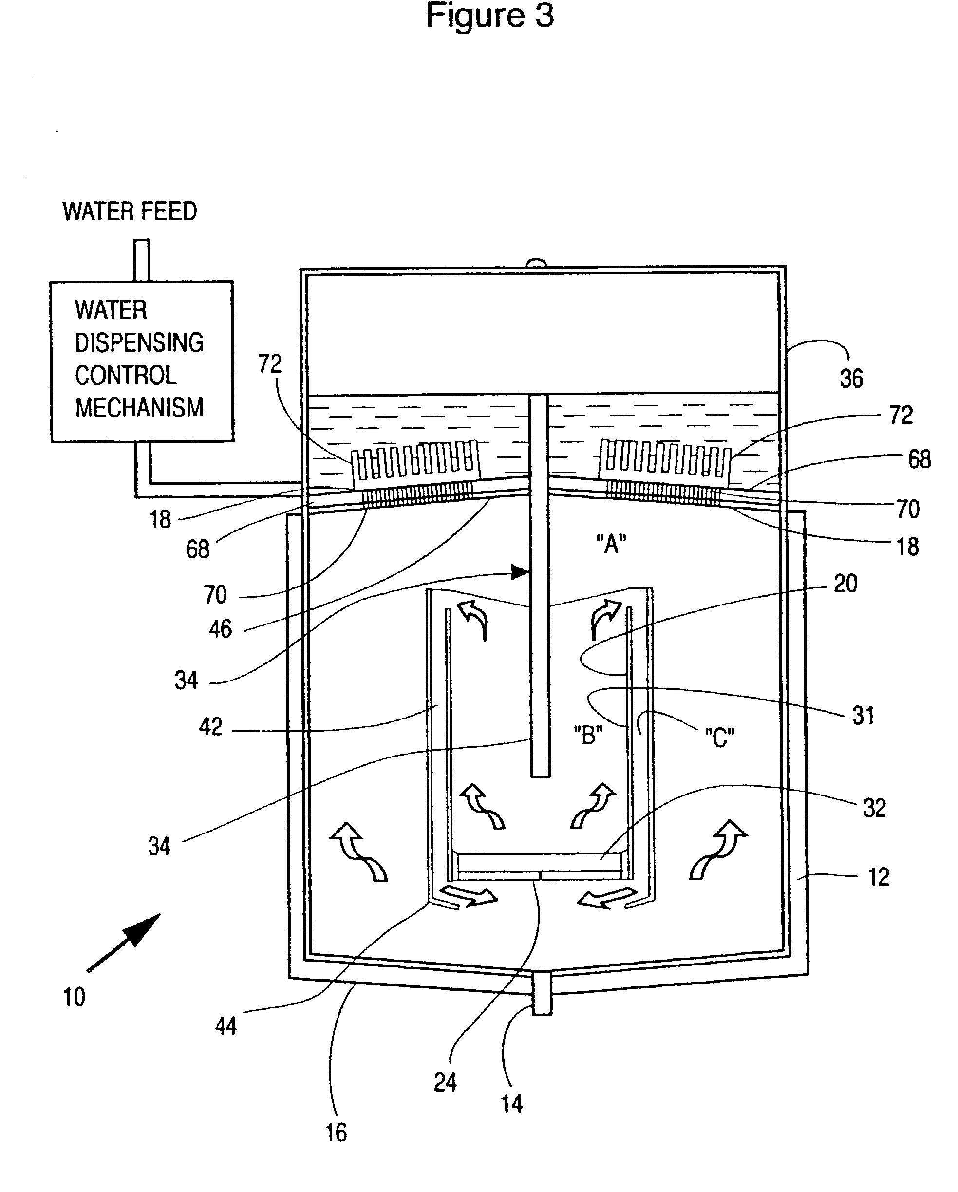
[0082] I have found that non-insulated surfaces of vapour-receiving chambers, conduits and the like enhance condensation of the vapour to reduce the load on the module colder surface. This advantageous arrangement can be enhanced by passing the feed liquid through or around the "cold" chamber to enhance condensation external of the module cooler surface and also pre-heat the feed water.
Problems solved by technology
However, the low rate of condensing causes a rapid pressure buildup inside the evaporation chamber, which results in both excess pressure and steam release into the environment.
Cascading of modules to increase the temperature differential between the hot and cold sides only decreases the heat pumping capability of the modules, and further reduce the condensing rate of the steam.
In fact, a similar analysis can be conducted to indicate that the embodiment described in DE3539086A1 is impractical for continuous use due to its inefficiency in any process that attempts to recover a liquid from a solvent solution by first evaporating the liquid and then condensing its vapour.
Method used
View moreImage
Smart ImageViewing Examples

Examples
example
[0120] With reference to the embodiment shown in FIG. 5, operative in a steady state mode, input feed water at a rate of 1 l / hr was heated to form steam by a module having eight Peltier units under approximately 3 amps at 14 volts to use 360-380 watts. This steam condensed on the cooler surface of the module to provide 400 ml water and the remaining 600 ml on the cooling coil and the top surface of the enclosure. This vapour sealed unit thus provided, by reason of thermal recycling, according to the invention, an approximately 50% reduction in electrical energy required to boil the water over conventional distillation processes.
Login to View More PUM
| Property | Measurement | Unit |
|---|---|---|
| Temperature | aaaaa | aaaaa |
| Flow rate | aaaaa | aaaaa |
| Boiling point | aaaaa | aaaaa |
Abstract
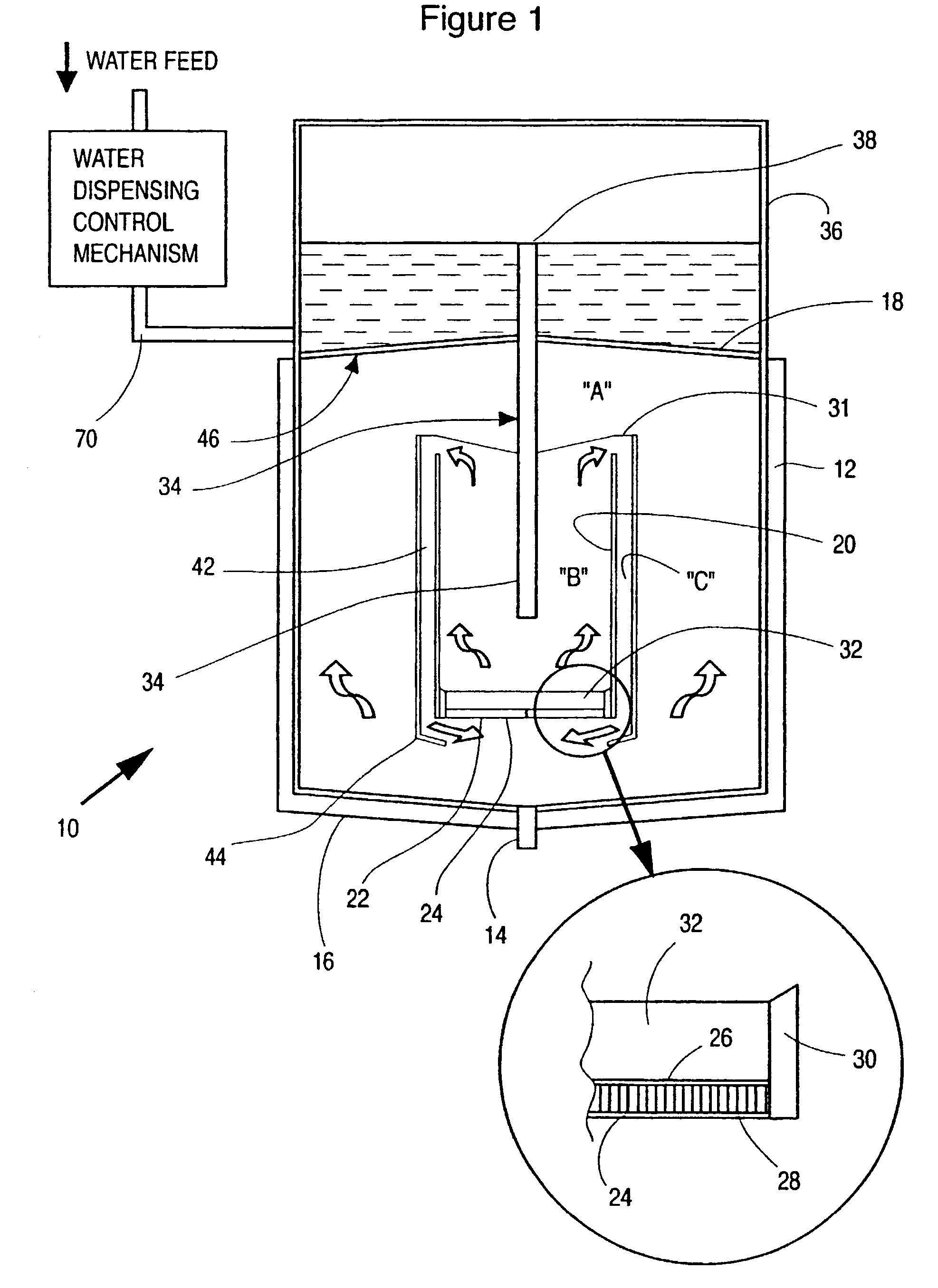
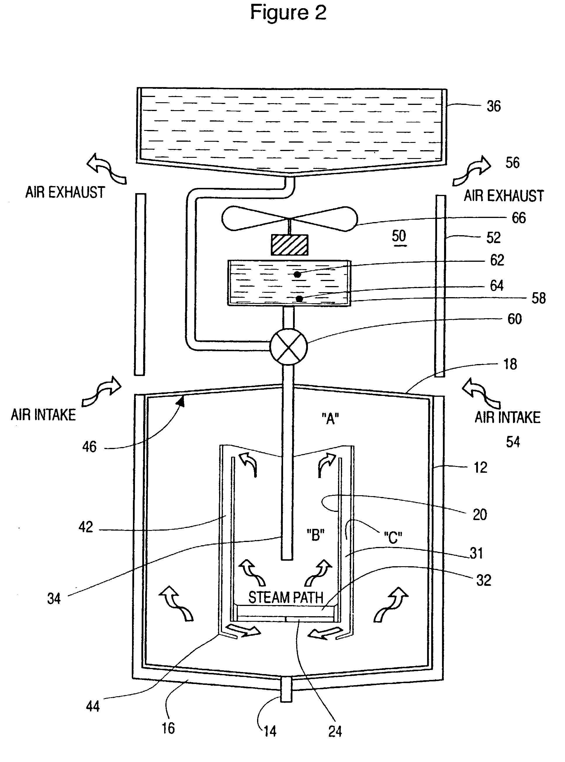
A process comprising electrically activating a thermoelectric module (24) to provide a first module heated surface (26) and a module cooler surface (28); feeding the impure liquid to the first module heated (26) surface to produce vapour of the liquid; and transferring the vapour to the module cooler surface (28) to effect heath transfer to the module cooler surface (28), the improvement comprising (a) directing a first portion of the vapour adjacent to or onto the module cooler surface (28) to effect heat transfer to the module cooler surface to produce a first condensed liquid (b) directing a second portion of the vapour to condenser means (18) comprising a second cooler surface (46) remote from the module cooler surface (28) to effect heat transfer to the second cooler surface (46) to produce a second condensed liquid; and (c) collecting the first and second condensed liquids; wherein the condensation means is such as to accept the balance of the latent heat contained in the vapour produced by the first module heated surface (26) which latent heat cannot be pumped from the module cooler surface (28) through the module to the first module heated surface (26) in order to maintain the process under continuous vapour flow.
Description
[0001] This invention relates to a process of purifying a liquid, particularly water, using a thermoelectric module; and apparatus of use in said process.BACKGROUND TO THE INVENTION[0002] Thermoelectric modules are small, solid state, heat pumps that cool, heat and generate power. In function, they are similar to conventional refrigerators in that they move heat from one area to another and, thus, create a temperature differential.[0003] A thermoelectric module is comprised of an array of semiconductor couples (P and N pellets) connected electrically in series and thermally in parallel, sandwiched between metallized ceramic substrates. In essence, if a thermoelectric module is connected to a DC power source, heat is absorbed at one end of the device to cool that end, while heat is rejected at the other end, where the temperature rises. This is known as the Peltier Effect. By reversing the current flow, the direction of the heat flow is reversed.[0004] It is known that a thermoelectr...
Claims
Login to View More Application Information
Patent Timeline
 IPC IPC(8): B01D1/00B01D5/00C02F1/04
CPCB01D1/0017B01D5/0036B01D5/0042B01D5/0066Y10S203/19Y10S159/01Y10S203/11Y10S203/09Y10S203/08C02F1/04
InventorDABLEH, YOUSSEF HANNA
OwnerDABLEH YOUSSEF HANNA