Automated method of and system for dimensioning objects over a conveyor belt structure by applying contouring tracing, vertice detection, corner point detection, and corner point reduction methods to two-dimensional range data maps of the space above the conveyor belt captured by an amplitude modulated laser scanning beam

a laser scanning and automatic technology, applied in the direction of sensing by electromagnetic radiation, using reradiation, instruments, etc., can solve the problems of inability to scan bar code systems in a true omni-directional sense, inability to achieve true omni-directional scanning along the principal planes of a large 3-d scanning volume, etc., to achieve a small degree of omni-directional scanning and reduce the depth of field

Inactive Publication Date: 2002-12-05
METROLOGIC INSTR
View PDF0 Cites 118 Cited by
  • Summary
  • Abstract
  • Description
  • Claims
  • Application Information

AI Technical Summary

Benefits of technology

[0008] Accordingly, a primary object of the present invention is to provide a novel tunnel-type automated package identification and measuring system that is free of the shortcomings and drawbacks of prior art tunnel-type laser scanning systems and methodologies.

Problems solved by technology

While over-the-head laser scanning systems are effective in scanning upwardly-facing bar codes on conveyed objects, there are many applications where it is not practical or otherwise feasible to ensure that bar code labels are upwardly-facing during transportation under the scanning station.
Notably, however, prior art tunnel scanning systems, including the system disclosed in U.S. Pat. No. 5,019,714, are incapable of scanning bar code systems in a true omni-directional sense, i.e. independent of the direction that the bar code faces as it is transported along the conveyor structure.
However, true omnidirectional scanning along the principal planes of a large 3-D scanning volume has not been hitherto possible.
Also, while numerous systems have been proposed for automatically identifying and measuring the dimensions and weight of packages along a high-speed conveyor, prior art systems have been very difficult to manufacture, maintain, and operate in a reliable manner without the use of human supervision.

Method used


Image

  • Automated method of and system for dimensioning objects over a conveyor belt structure by applying contouring tracing, vertice detection, corner point detection, and corner point reduction methods to two-dimensional range data maps of the space above the conveyor belt captured by an amplitude modulated laser scanning beam
  • Automated method of and system for dimensioning objects over a conveyor belt structure by applying contouring tracing, vertice detection, corner point detection, and corner point reduction methods to two-dimensional range data maps of the space above the conveyor belt captured by an amplitude modulated laser scanning beam
  • Automated method of and system for dimensioning objects over a conveyor belt structure by applying contouring tracing, vertice detection, corner point detection, and corner point reduction methods to two-dimensional range data maps of the space above the conveyor belt captured by an amplitude modulated laser scanning beam

Examples


embodiment 1

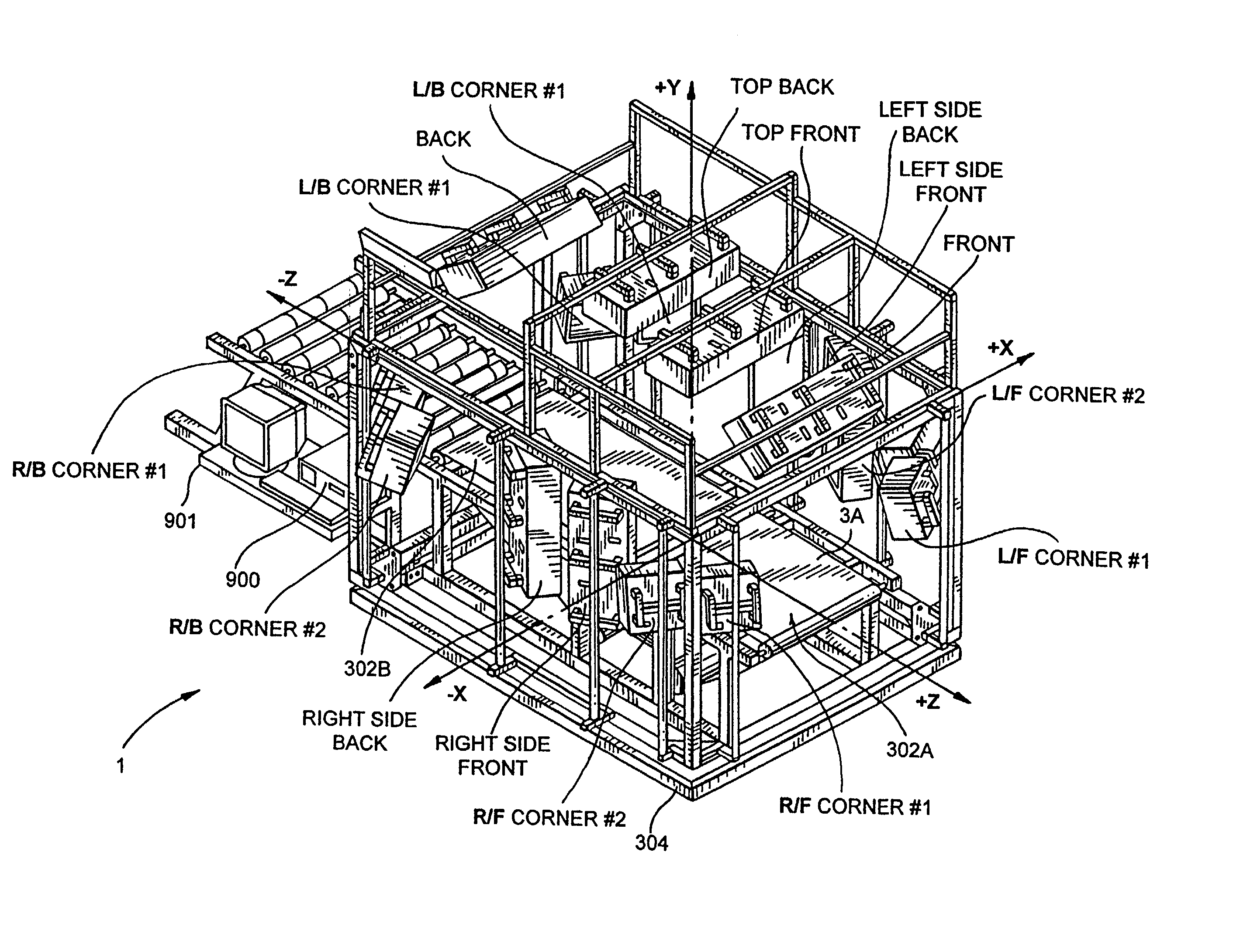
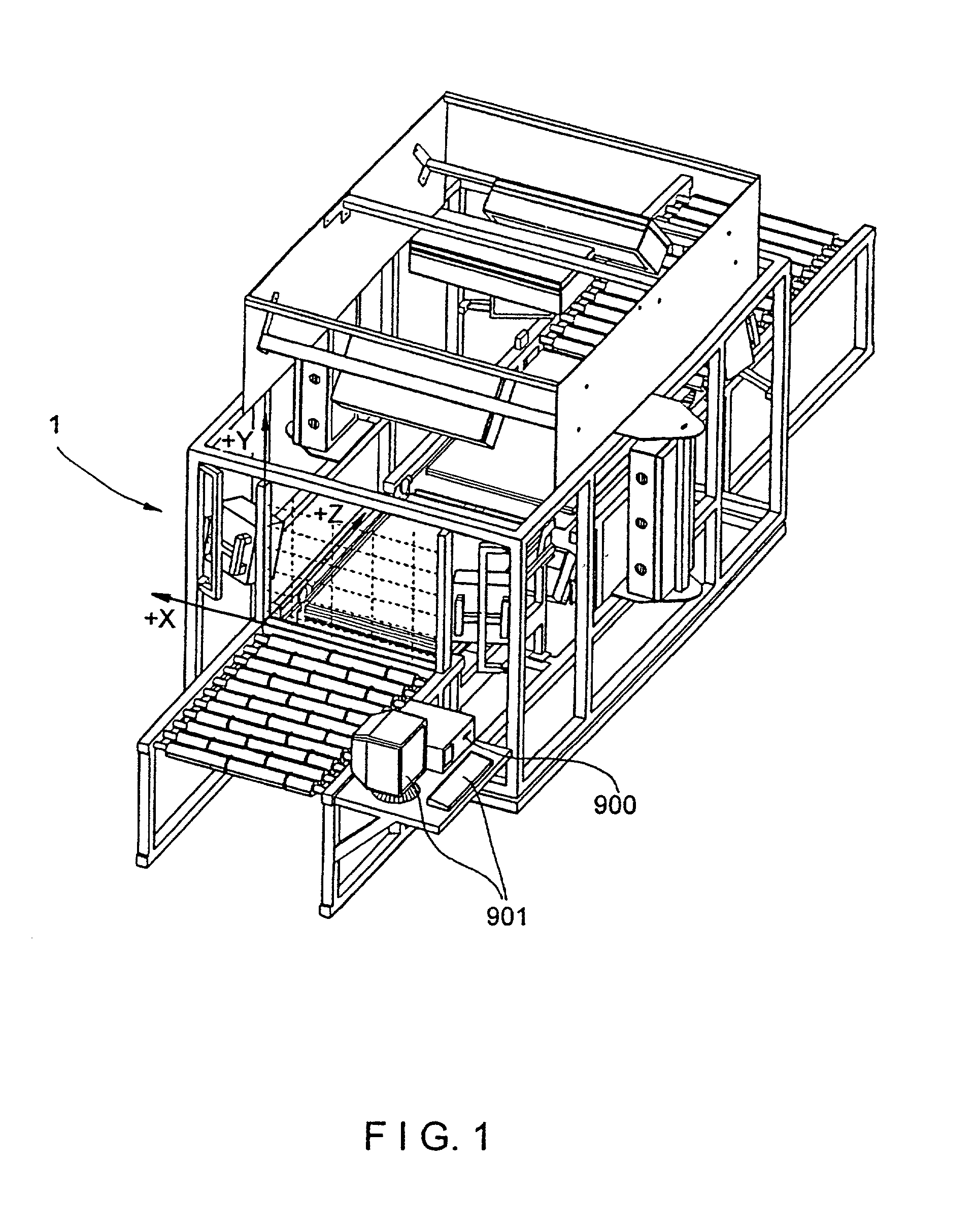
[0310] As shown in FIGS. 1 through 1E, the tunnel scanning system of the first illustrative embodiment 1 comprises an arrangement of laser scanning subsystems (i.e. scanners) which, by virtue of their placement, relative to the conveyor belt subsystem 300, essentially form a "tunnel" scanning subsystem over and about the conveyor belt of the conveyor subsystem 300. In the field of package sortation of any sort, whether it be mail, luggage (as in an airport terminal) or other items or boxes, this type of code symbol scanning system is known as a "tunnel scanning system" by those skilled in the art.

[0311] The tunnel scanning system of the first illustrative embodiment, shown in great detail in FIGS. 1 through 32B, can be designed and constructed to meet any specific set of customer-defined scanning parameters. For example, in the first illustrative embodiment, the bar code label can be on any one side of a box having six or more sides. The bar code label could be in any orientation. F...

embodiment 2000

[0489] Referring now to FIGS. 33 through 34, the "dual-lane" automated tunnel-type laser scanning system of the second illustrated embodiment 2000 will now be described in detail. As in the first illustrative embodiment depicted in FIGS. 1 through 32B, the system of the second illustrative embodiment is designed to identify and measure packages that are singulated along a conveyor subsystem in a conventional manner.

[0490] Overview of the Tunnel Scanning System of the Second Illustrative Embodiment of the Present Invention

[0491] As shown in FIGS. 33 and 34, the automated tunnel scanning system of the second illustrative embodiment indicated by reference numeral 2000 comprises an integration of subsystems, namely: a high-speed package conveyor system 2100 having a conveyor belt 2101 having a width of at least 60 inches to support a pair of package transport lanes along the conveyor belt; a first pair of triple-disc holographic laser scanning bar code symbol reading subsystems 2200A an...

first embodiment

[0546] Notably, the holographic LADAR-based imaging and dimensioning systems 3301B described above, without modification, can also function as compact single-line, laser scanner having very large depth of field, reduced optical throw, and laser scan lines with minimum curvature (i.e. minimum bow). The single line scanner uses a holographic disk to create a sequence of scan lines that all leave the disk at the same diffraction angle but have different focal lengths. In this scanner described above, the resulting linear scan pattern has six focal planes, providing a very large depth of field for high density bar codes. As mentioned above, six different holographic facets for the six focal planes are spatially repeated three times around the disk for a total of eighteen facets on the scanning disk. This replication of the basic scan pattern results in a high speed scanner.


PUM


Abstract

A fully automated package identification and measuring system, in which an omni-directional holographic scanning tunnel is used to read bar codes on packages entering the tunnel, while a package dimensioning subsystem is used to capture information about the package prior to entry into the tunnel. Mathematical models are created on a real-time basis for the geometry of the package and the position of the laser scanning beam used to read the bar code symbol thereon. The mathematical models are analyzed to determine if collected and queued package identification data is spatially and / or temporally correlated with package measurement data using vector-based ray-tracing methods, homogeneous transformations, and object-oriented decision logic so as to enable simultaneous tracking of multiple packages being transported through the scanning tunnel.

Description

[0001] 1. Field of Invention[0002] The present invention relates generally to an automated tunnel-type laser scanning package identification and measuring system arranged about a high-speed conveyor structure used in diverse package routing and transport applications, and also a method of identifying and measuring packages labeled with bar code symbols.[0003] 2. Brief Description of the Prior Art[0004] In many environments, there is a great need to automatically identify and measure objects (e.g. packages, parcels, products, luggage, etc.) as they are transported along a conveyor structure. While over-the-head laser scanning systems are effective in scanning upwardly-facing bar codes on conveyed objects, there are many applications where it is not practical or otherwise feasible to ensure that bar code labels are upwardly-facing during transportation under the scanning station.[0005] Various types of "tunnel" scanning systems have been proposed so that bar codes can be scanned indep...

Claims


Application Information

Patent Timeline
Patent Type & Authority Applications(United States)
IPC IPC(8): G01S17/89G02B26/10G06K7/10G06K7/14G06K17/00G07G1/00H01L21/285H01L29/45
CPCB82Y15/00H01L29/452G01S7/4818G01S17/58G01S17/88G01S17/89G02B26/106G06K7/10G06K7/10564G06K7/10584G06K7/10594G06K7/10603G06K7/10663G06K7/10673G06K7/10693G06K7/10702G06K7/10722G06K7/10792G06K7/10801G06K7/10811G06K7/10851G06K7/10861G06K7/10871G06K7/10881G06K7/10891G06K7/109G06K7/14G06K17/0022G06K2207/1013G07F11/002G07G1/0054H01L21/28575G01S7/4817G07F9/002
Inventor ZHU, XIAOXUNAU, KA MANGERMAINE, GENNADYGOOD, TIMOTHY A.SCHNEE, MICHAELSCOTT, IANGROOT, JOHNWILZ, DAVID M. SR.ROCKSTEIN, GEORGE B.BLAKE, ROBERT E.DICKSON, LEROYKNOWLES, CARL HARRY
Owner METROLOGIC INSTR
Why Eureka
Try Eureka