System and method for performing time domain reflectometry using gaussian pulses

a time domain and pulse technology, applied in the field of digital signal processing, can solve problems such as problems such as problems such as the use of step functions or signals, the degradation of the performance of devices or transmission mediums, and the amount of effort spen

Inactive Publication Date: 2002-12-05
NATIONAL INSTRUMENTS
View PDF5 Cites 16 Cited by
  • Summary
  • Abstract
  • Description
  • Claims
  • Application Information

AI Technical Summary

Problems solved by technology

These impedance changes can substantially degrade the performance of a device or transmission medium, and so a great deal of effort has been spent detecting and analyzing such interconnect discontinuities.
However, there are a number of drawbacks to this approach.
The use of a step function or signal is problematic because the steep rise of the leading edge of the step entails many high frequency signal components.
Transmission media and electronic and optical components behave differently for different frequencies, leading to such distorting effects as dispersion and dissipation of the pulse energy.
The effect of dispersion is particularly troublesome for step pulses in TDR applications because the leading edge of the step is used to determine the timing of the pulse.
The dispersion of high frequency components in the edge can smooth the edge to such a degree that precise timing of the reflected pulse may be difficult or even impossible.
Current systems developed to perform TDR with step pulses involve extremely high speed sampling and tend to be very expensive, costing on the order of one hundred thousand dollars each.
However, there are currently no known systems or methods to perform TDR with Gaussian pulses, due to difficulties in accurately detecting, timing, and characterizing Gaussian pulses in a noisy medium.

Method used


Image

  • System and method for performing time domain reflectometry using gaussian pulses
  • System and method for performing time domain reflectometry using gaussian pulses
  • System and method for performing time domain reflectometry using gaussian pulses

Examples


Embodiment Construction

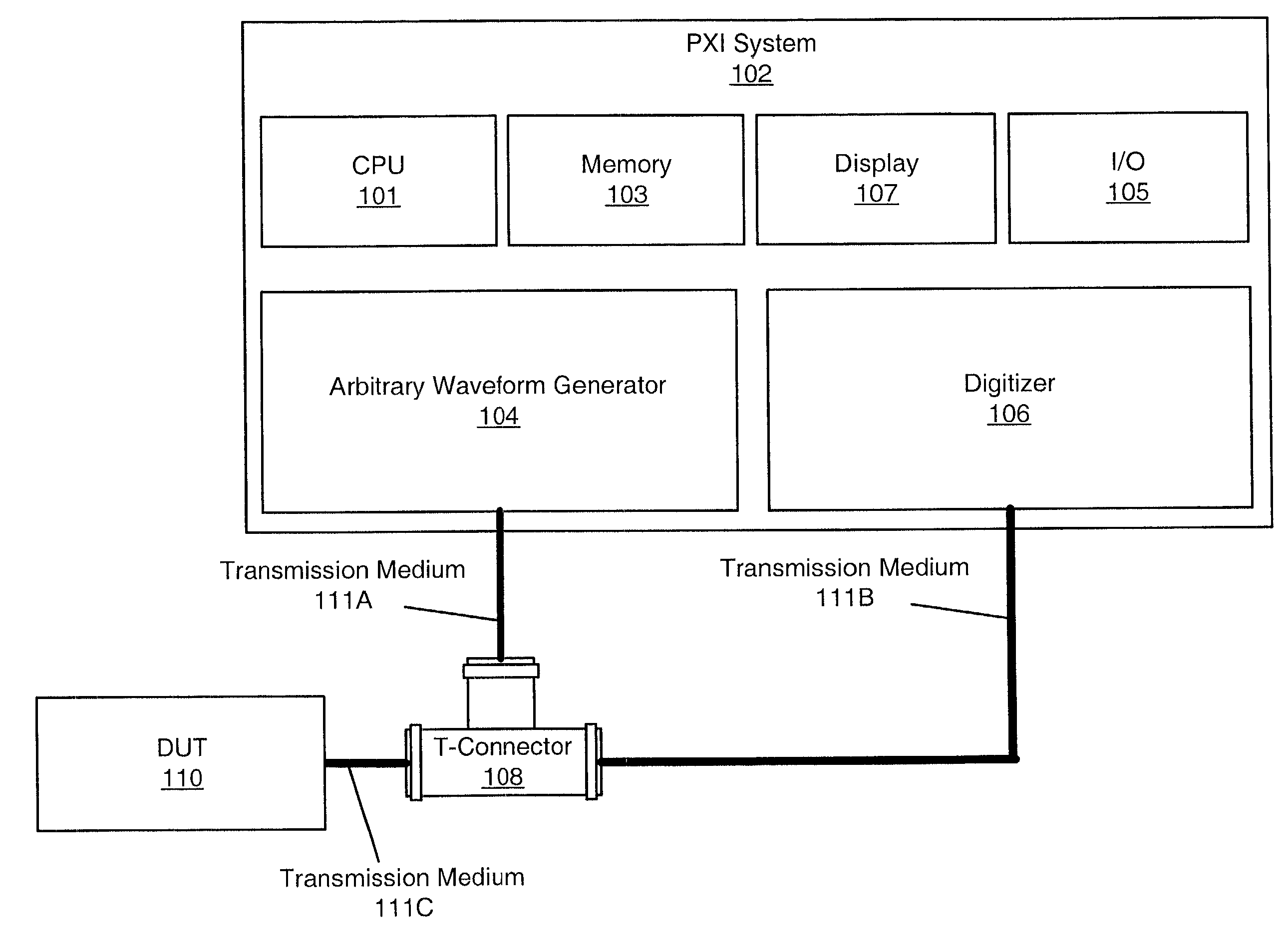
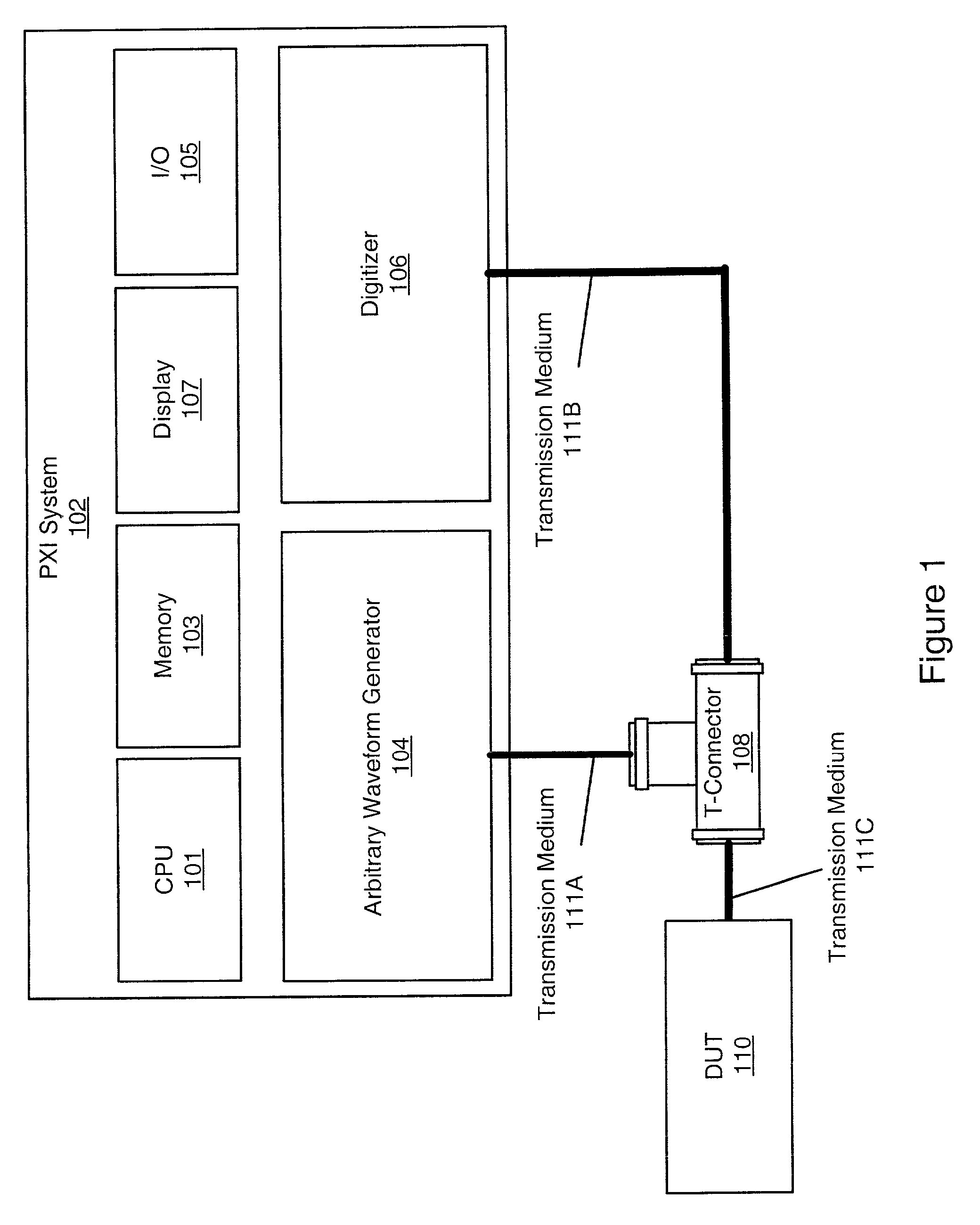
[0029] FIG. 1--A Gaussian Pulse TDR System

[0030] FIG. 1 is a block diagram of a Gaussian pulse TDR system, according to one embodiment. As FIG. 1 shows, a computer system 102 may comprise a CPU 101, a memory 103, a display 107, and an I / O interface 105. In the preferred embodiment, the computer system 102 comprises a PCI eXtensions for Instrumentation (PXI) system which includes one or more PXI computer boards or cards plugged into a PXI backplane, such as a "PC on a card", housed in a PXI chassis. In other words, the PXI cards may comprise the memory 103 and CPU 101 which are operable to respectively store and execute one or more computer software programs implementing the present invention. As FIG. 1 also shows, in one embodiment, the PXI system 102 may also include display 107, such as a monitor, for displaying visual information, such as results, to a user, as well as I / O interface 105 for receiving input and sending output to external systems or components. In one embodiment, t...


PUM

PropertyMeasurementUnit
Timeaaaaaaaaaa
areaaaaaaaaaaa
power spectrumaaaaaaaaaa

Abstract

System and method for performing Time Domain Reflectometry (TDR) on a Device Under Test (DUT) using Gaussian pulses. A signal is received comprising an initial Gaussian pulse and one or more reflected pulses from the DUT. Each pulse is characterized by determining a set of estimated parameters, permuting the estimated parameter set to generate one or more permuted parameter sets, generating linear equations from the parameter sets, including parameter variables for the corresponding Gaussian pulse, and determining values for the parameter variables by solving the linear equations. The determined parameters characterize the Gaussian pulse. If there are N parameters to determine and M permutations generated, where M is greater than or equal to N, M+1 linear equations are solved to overdetermine the N parameters. The determined parameters of the initial pulse and the one or more reflected pulses are useable to perform TDR analysis on the DUT.

Description

[0001] The present invention relates generally to the field of digital signal processing, and more particularly to the use of Gaussian pulses to perform Time Domain Reflectometry to locate and characterize faults in a Device Under Test.DESCRIPTION OF THE RELATED ART[0002] In the field of digital signal processing there is often a need to detect a signal pulse in a transmission medium, such as an electrical cable or optical fiber, or an electronic or optical device. For example, in electronic or optical systems, when a signal encounters a change in impedance in the transmission medium, a partial reflectance of the signal occurs, decreasing the amplitude of the propagated signal. These impedance changes can substantially degrade the performance of a device or transmission medium, and so a great deal of effort has been spent detecting and analyzing such interconnect discontinuities.[0003] One technique which has been used to great effect in this area is Time Domain Reflectometry (TDR)....

Claims


Application Information

Patent Timeline
Patent Type & Authority Applications(United States)
IPC IPC(8): G01M11/00
CPCG01M11/3145
Inventor QIAN, SHIEZHANG, NANXIONG
Owner NATIONAL INSTRUMENTS
Why Eureka
Try Eureka