
Laser machining system and method

a laser machining and laser machining technology, applied in the direction of active medium materials, manufacturing tools, welding/soldering/cutting articles, etc., can solve the problems of increasing the amount of accumulated heat in the material, the need for several post-laser machining process steps, and the inability to remove debris by conventional washing techniques, etc., to reduce the deposition of debris and reduce the thermal damage of the substrate

Inactive Publication Date: 2011-02-15
XSIL TECH
View PDF40 Cites 42 Cited by
  • Summary
  • Abstract
  • Description
  • Claims
  • Application Information

AI Technical Summary

Benefits of technology

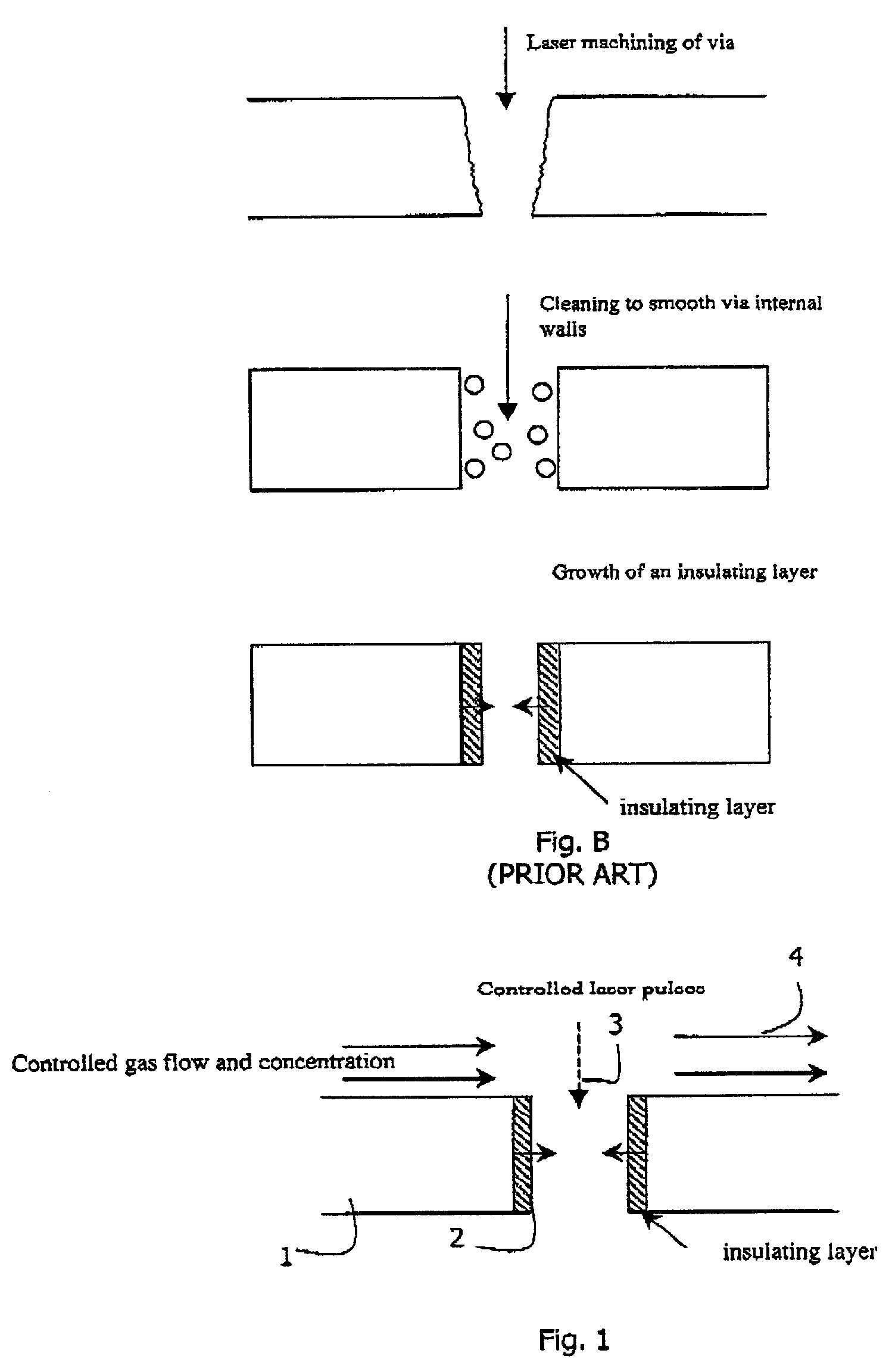
[0027]In one embodiment, the gas handling system comprises means for controlling the gaseous environment to enhance removal of debris from the machining site and locality or to reduce the quantity of debris that is generated.
[0097]In one embodiment, angled vias are used to reduce the size of a device by allowing connection pads to be placed on the back side of the die.

Problems solved by technology

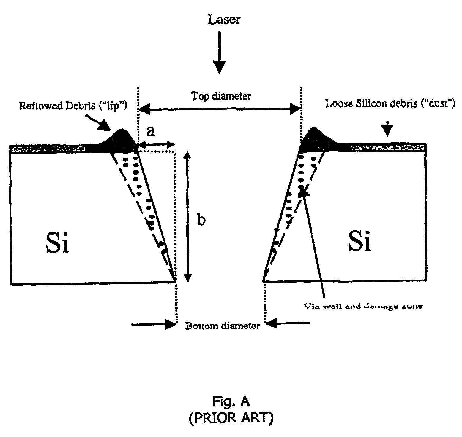
Typically, using a laser beam to machine vias results in several problems.
These problems result in the requirement for several post laser machining process steps.
Typically the debris cannot be removed by conventional washing techniques.
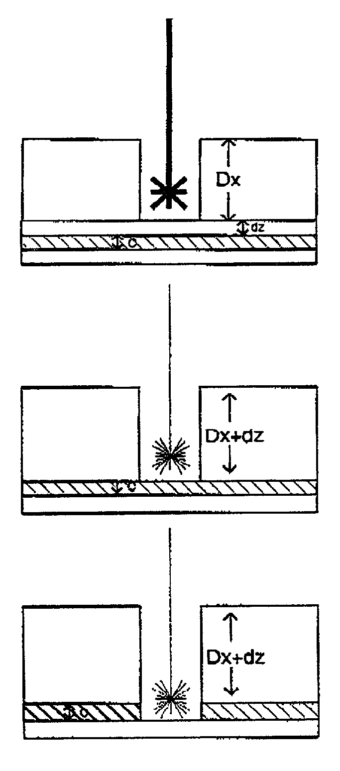
A second problem that occurs for via drilling is that the accumulated heat in the material increases as the pulse rate, pulse energy and total number of pulses of laser light into the material are increased.
At some point the heat dissipated into the surrounding material can cause severe thermal damage to the internal walls of the structure.
The impact of thermal damage is to reduce structural integrity due to microcracking and crystal deformation.
This however reduces the total energy delivered to the surface and is not an efficient technique.
Using conventional techniques it is not possible to control the sidewall material composition or conductivity.

Method used


Image

  • Laser machining system and method
  • Laser machining system and method
  • Laser machining system and method

Examples


example 1

[0181]In a process of drilling 1000 vias in a galvo field of 15 mmυ15 mm at a laser repetition rate of 55 kHz, using two pulses on each via and 50 machining steps, for a jump speed of 5 m / sec and a jump delay of 50 ∉s. The total distance between all the vias is ˜0.48 m.

[0182]The machining speed can be estimated as below:

[0183]∋tR⁢⁢R=155000=18.19⁢Π⁢⁢s=18.19⁢υ10-6⁢⁢sec.[0184]NVia / field=1000[0185]J_Speed=5 m / sec[0186]J_Delay=50 ∉s=50υ10−6 sec[0187]NT—Delay=2 (for 2 pulse on each step)[0188]NStep=50

[0189]Vmach=100050⁢↔♠←⁢1000⁢υ2υ18.19⁢υ106♣◆♡⁢0.485⁢•÷≠50⁢υ106⁢υ1000⁢=≈¨⁢~110⁢⁢vias / sec.

[0190]The above example describes a specific case where the laser pulse parameters remain unchanged throughout the multi-step process. However, if the laser pulse properties such as inter-pulse separation (tRR) and the number of pulses per step (NT—Delay) change from step to step, the denominator of equation (1.1) need to be replaced by the total sum of t1, t2 and t3 for each step.

Formation of Blind Microvi...


PUM

PropertyMeasurementUnit
repetition frequencyaaaaaaaaaa
diameteraaaaaaaaaa
pressuresaaaaaaaaaa

Abstract

A substrate (16) is machined to form, for example, a via. The substrate is in a chamber (15) within which the gaseous environment is controlled. The machining laser beam (13) is delivered with control of parameters such as pulsing parameters to achieve desired effects. The gaseous environment may be controlled to control integral development of an insulating lining for a via, thereby avoiding the need for downstream etching and oxide growth steps. Also, machining may be performed in multiple passes in order to minimize thermal damage and to achieve other desired effects such as a particular via geometry.

Description

[0001]The invention relates to laser machining of substrates.[0002]Laser drilling of micro-vias with pulsed lasers may be performed using two methods. In the first method a stationary beam is used (pixel vias): Using this technique a number of laser pulses are delivered to a single point on the substrate. The number of pulses required to reach a certain depth depends on their energy. This technique is suitable for vias smaller than approximately 100 microns diameter. The exact via diameter depends on the laser beam diameter, optical and laser parameters and material properties.[0003]In another method a beam is scanned along the outer profile of the via. This technique is suitable for vias larger than approximately 100 microns diameter. The laser moves in a circular pattern, in one or more concentric circles. Several repetitions might be required to reach the required depth. The via diameter is a function of the radius of the outer circle and the beam diameter. Such a via is referred...

Claims


Application Information

Patent Timeline
Patent Type & Authority Patents(United States)
IPC IPC(8): H01L21/302B23K26/00B23K26/06B23K26/12B23K26/14B23K26/38B23K101/40H01L21/461H05K3/00
CPCB23K26/063B23K26/127B23K26/123B23K26/125B23K26/1405B23K26/1458B23K26/383B23K26/386B23K26/388B23K26/409B23K26/16B23K26/073B23K26/385B23K26/12B23K2201/40B23K2203/12H05K3/0026Y10S438/94B23K26/1462B23K26/142B23K26/0622B23K26/384B23K26/40B23K26/389B23K2101/40B23K2103/12B23K2103/172H01S3/00
Inventor BOYLE, ADRIANMEIGHAN, OONAGHWALSH, GILLIANMAH, KIA WOON
Owner XSIL TECH
Learn More