Acousto-optic deflector applications in laser processing of dielectric or other materials

a dielectric or other material laser processing and acousto-optic technology, applied in the direction of manufacturing tools, metal working equipment, welding/soldering/cutting articles, etc., can solve the problem that the variation of the trajectory angle may require high beam position acceleration, the acceleration and/or velocity of acceleration and/or velocity may be difficult to achieve in traditional laser processing machines, and the optical system may have significant time delays. the effect of widening the laser beam spo

Active Publication Date: 2010-12-02
ELECTRO SCI IND INC
View PDF29 Cites 91 Cited by
  • Summary
  • Abstract
  • Description
  • Claims
  • Application Information

AI Technical Summary

Benefits of technology

[0014]In one embodiment, a method is provided for processing features in a workpiece with a series of laser pulses. The method includes imparting, using a first positioning system, first relative movement of a laser beam spot position along a processing trajectory. The method also includes imparting, using a second positioning system, second relative movement of the laser beam spot position along a dither direction relative to the processing trajectory. The second relative movement is superimposed on the first relative movement, and the second relative movement is at a substantially higher velocity than that of the first relative movement. The method further includes emitting a first plurality of laser pulses during the second relative movement to effectively widen a laser beam spot at the workpiece in the dither direction, and varying an intensity profile of the first plurality of laser pulses as a function of deflection position along the dither direction to selectively shape a first feature in the dither direction.

Problems solved by technology

These optical systems may have significant time delays (e.g., about 10 milliseconds (ms) to about 10 s) when changing laser processing spot characteristics.
Other problems are associated with building a machine to meet the processing parameters noted above.
When processing traces at high velocity, the variation in trajectory angle may require high beam position acceleration at very short time scales.
Such accelerations and / or velocities may be difficult to achieve in traditional laser processing machines, which have relied on beam positioning technologies such as linear stages in combination with mirror galvanometer beam deflectors (referred to herein as “galvos” or “galvo mirrors”), along with static (or slowly varying) beam conditioning optics that cannot respond in the time scales used for this type of processing (e.g., on the order of about 1 microsecond (μs) to about 100 μs).
However, at low velocities, the applied power may become so low that the peak pulse power may be insufficient to ablate the material without inducing thermal effects (e.g., melting and charring).
Another processing effect that can reduce ablation efficiency may be the interaction of the processing beam with the plume of ablated material.
Plumes may distort or deflect the beam enough to disrupt the focused beam, or cause accuracy issues due to its deflection.
However, these references do not describe obtaining the desired performance in advanced beam positioner designs.

Method used


Image

  • Acousto-optic deflector applications in laser processing of dielectric or other materials
  • Acousto-optic deflector applications in laser processing of dielectric or other materials
  • Acousto-optic deflector applications in laser processing of dielectric or other materials

Examples


Embodiment Construction

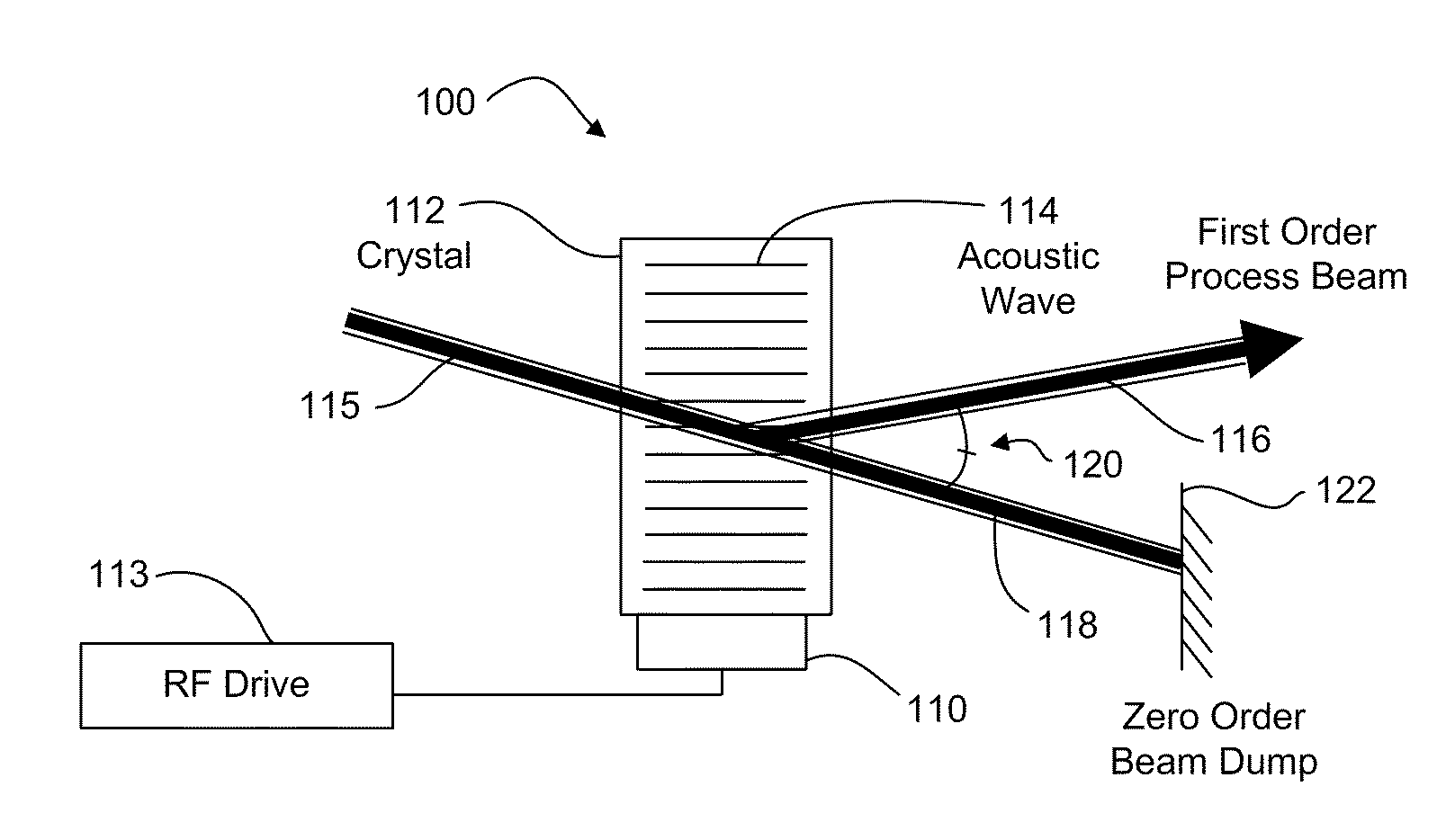
[0058]Embodiments disclosed herein provide flexible, high-speed beam positioning and conditioning that is economical and feasible. This disclosure describes the use of AODs in combination with linear positioning stages and / or galvos.

[0059]While the example embodiments disclosed herein are directed to AODs, electro-optic deflectors (EODs) may also be used. In certain embodiments, for example, EODs are suitable replacements for some or all AOD pointing (deflection) functions. EODs (when set up for angular deflection) do not typically modulate power. Thus, in certain embodiments, one or more AODs are used for power modulation and one or more EODs are used for pointing. Acousto-optic devices that perform modulation may be referred to herein as acousto-optic modulators (AOMs). Other mechanical beam steering technologies such as fast-steering mirrors (FSMs) may be substituted for the galvo beam positioning subsystem without loss of functionality.

[0060]A laser processing system, according ...


PUM

PropertyMeasurementUnit
speedaaaaaaaaaa
time delaysaaaaaaaaaa
velocitiesaaaaaaaaaa

Abstract

A laser processing system for micromachining a workpiece includes a laser source to generate laser pulses for processing a feature in a workpiece, a galvanometer-driven (galvo) subsystem to impart a first relative movement of a laser beam spot position along a processing trajectory with respect to the surface of the workpiece, and an acousto-optic deflector (AOD) subsystem to effectively widen a laser beam spot along a direction perpendicular to the processing trajectory. The AOD subsystem may include a combination of AODs and electro-optic deflectors. The AOD subsystem may vary an intensity profile of laser pulses as a function of deflection position along a dither direction to selectively shape the feature in the dither direction. The shaping may be used to intersect features on the workpiece. The AOD subsystem may also provide rastering, galvo error position correction, power modulation, and/or through-the-lens viewing of and alignment to the workpiece.

Description

RELATED APPLICATION[0001]This application claims the benefit under 35 U.S.C. § 119(e) of U.S. Provisional Application No. 61 / 181,889, filed May 28, 2009, which is hereby incorporated by reference herein in its entirety.TECHNICAL FIELD[0002]This disclosure is related to laser processing of dielectric or other materials.BACKGROUND INFORMATION[0003]Laser processing of dielectric and conductive materials is commonly used to ablate fine features in electronic components. For example, chip packaging substrates may be laser processed in order to route signals from the semiconductor die to a ball-grid array or similar package. Laser processed features may include signal traces, ground traces, and microvias (to connect signal traces between package layers). A recent design trend incorporates signal and ground traces on a single layer to tightly control signal impedance while reducing the number of layers in a chip package. Such an approach may require small feature dimensions and spacing (e....

Claims


Application Information

Patent Timeline
Patent Type & Authority Applications(United States)
IPC IPC(8): B23K26/00B23K26/073
CPCB23K26/0648B23K26/0665B23K26/0807B23K26/08B23K2201/40B23K26/032B23K26/046B23K26/4075B23K26/082B23K26/40B23K2101/40B23K2103/50B23K2103/56
Inventor UNRATH, MARK A.JORDENS, WILLIAM J.ISMAIL, JAMESMATSUMOTO, HISASHILINEBURG, BRIAN J.
Owner ELECTRO SCI IND INC
Why Eureka
Try Eureka