Slider air bearing surface having improved fly height profile characteristics

a slider and air bearing technology, applied in the direction of magnetic recording, information storage, maintaining head carrier alignment, etc., can solve the problems of hard disk drive non-operation, damage to the head or disk, suspension damage,

Inactive Publication Date: 2002-12-05
HITACHI GLOBAL STORAGE TECH NETHERLANDS BV
View PDF5 Cites 28 Cited by
  • Summary
  • Abstract
  • Description
  • Claims
  • Application Information

AI Technical Summary

Problems solved by technology

Stiction results when the air bearing surface (ABS) of the slider has been in stationary contact with the disk for a period of time and tends to resist translational movement or "sticks" to the disk surface.
Excessively high stiction force can cause hard disk drive non-operable because the spindle motor current may not be enough to overcome the adhesion force between the slider and disk.
Stiction can also result in damage to the head or disk when the slider suddenly breaks free from the disk surface when disk rotation is initiated.
In addition, because the suspension between the actuator and the slider is relatively fragile to permit the slider to fly above the disk surface, sudden rotation of the disk can also damage the suspension.
The main problem with the imparting higher bump height of laser texture to the landing zone area of the disk is that it brings the disk surface that much closer to a flying head.
The margin between the flying height and the top most region of the texture area is reduced, thereby increasing the potential for head disk contact and hence the possibility of a head crash.
However, the fly heights achieved by the prior art ABS slider designs are not suitable for low fly height products due to its inability to fly low in addition to meeting other operating factors such as fly height sensitivity, altitude loss, and seek loss.
As the pressure to increase recording density forces lower flying heights, the balance between maintaining bump height on the landing zone and the need to fly lower on the data zone is a difficult challenge.

Method used


Image

  • Slider air bearing surface having improved fly height profile characteristics
  • Slider air bearing surface having improved fly height profile characteristics
  • Slider air bearing surface having improved fly height profile characteristics

Examples


Embodiment Construction

[0020] This invention is described in a preferred embodiment in the following description with references to the following figures. While this invention is described in terms of the best mode of achieving this invention's objectives, it will be appreciated by those skilled in the art that variation may be accomplished in view of these teachings without deviating from the spirit or scope of the invention.

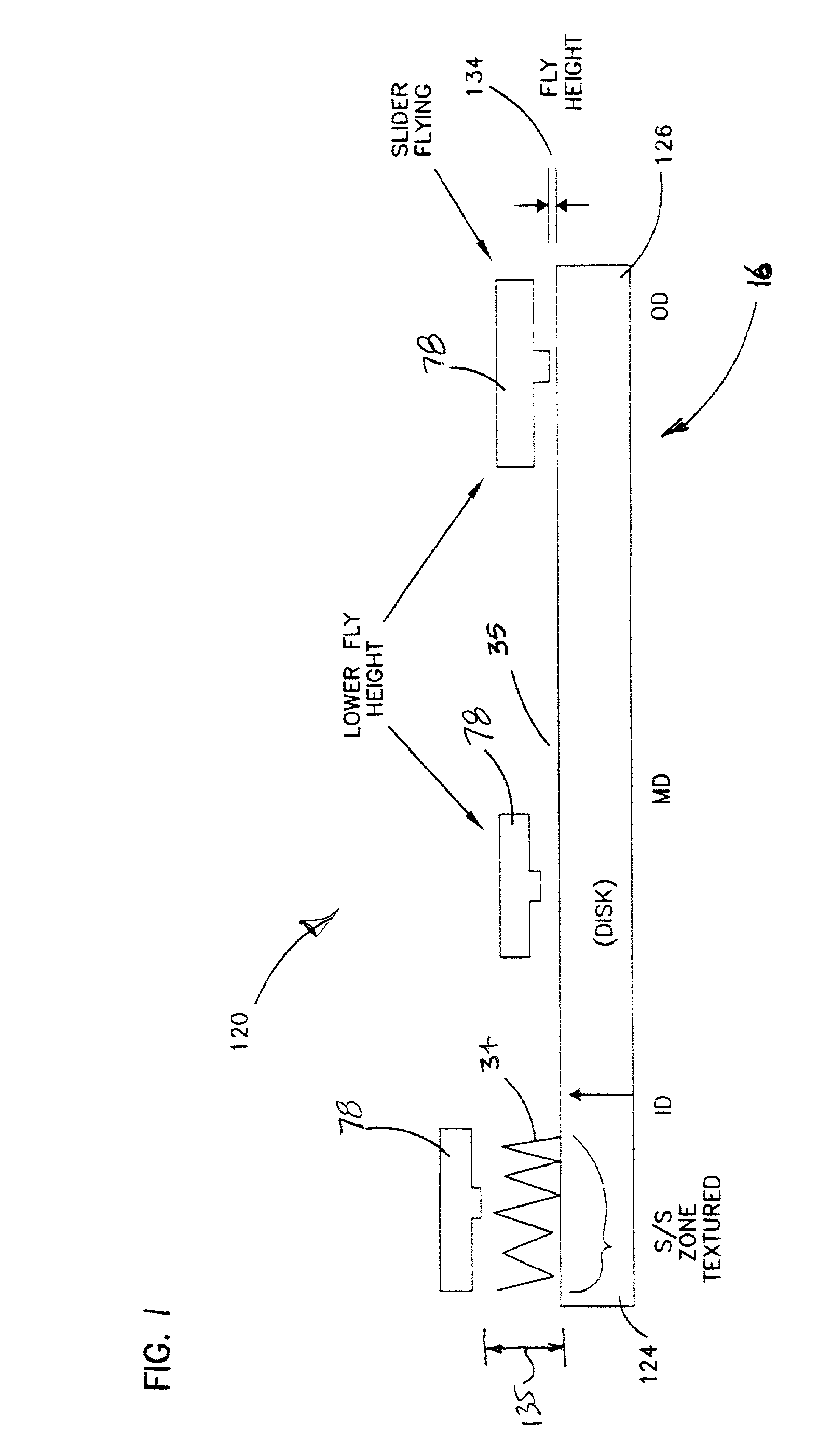
[0021] FIG. 1 illustrates a disk / slider combination 120 in accordance with the present invention. The disk 16 has an inner diameter 124 and an outer diameter 126. At the inner diameter 124 is a laser textured start-stop landing zone 34 to decrease stiction. The remaining portion of the disk 16 is a relatively smooth magnetic recording surface 35. Those skilled in the art will recognize that the entire surface of the disk 16 may include a textured surface. However, those skilled in the art will recognize that the texture is much more coarse over the landing zone 34. Accordingly, the t...


PUM

PropertyMeasurementUnit
heightaaaaaaaaaa
heightaaaaaaaaaa
angleaaaaaaaaaa

Abstract

A dual depth slider air bearing surface that enables the slider to achieve a ramp fly height profile near the textured landing zone of a disk. The air bearing slider includes a slider body on which a U-shaped leading ABS pad is defined near and along a leading edge (relative to a moving recording medium) and partially along each side of the slider body. A front step pad extends from the leading edge section of the leading ABS pad to the leading edge of the slider body, at a reduced height relative to the height of the ABS pad. An asymmetric rear pad is defined along a longitudinal axis of the slider body and proximate to a trailing edge of the slider body. Extending above the rear pad is a trailing ABS pad, which has an asymmetric profile with respect to the longitudinal axis of the slider. The trailing ABS pad has a curved bowing profile towards the front of the slider body on the leading edge side of the trailing ABS pad.

Description

[0001] 1. Field of the Invention[0002] This invention relates in general to magnetic recording disk drives, and more particularly to the configuration of the air bearing surface of a slider for use in a contact start / stop magnetic disk drive.[0003] 2. Description of Related Art[0004] Disk drives are storage devices that use a rotatable disk with concentric data tracks containing information, a head or transducer for reading and / or writing data onto various tracks, and an actuator connected to a carrier for the head moving the head to the desired track and maintaining it over the track centerline during read or write operations. There are typically a plurality of disks separated by spacer rings and stacked on a hub that is rotated by a disk drive motor. A housing supports the drive motor and head actuator and surrounds the head and disk to provide a substantially sealed environment for the head-disk interface.[0005] In typical magnetic recording disk drives, the head carrier is an ai...

Claims


Application Information

Patent Timeline
Patent Type & Authority Applications(United States)
IPC IPC(8): G11B5/60G11B21/21
CPCG11B21/21G11B5/6005
Inventor KANG, SOO-CHOON
Owner HITACHI GLOBAL STORAGE TECH NETHERLANDS BV
Why Eureka
Try Eureka