Diode lighting system

a lighting system and diode technology, applied in the direction of printed circuit assembling, coupling device connection, printed circuit non-printed electric component association, etc., can solve the problems of limited number of leds that can be used, light system, and no prior art disclosures named in the name are applicable to large scal

Active Publication Date: 2002-12-05
ALTMAN STAGE LIGHTING
View PDF12 Cites 122 Cited by
  • Summary
  • Abstract
  • Description
  • Claims
  • Application Information

AI Technical Summary

Problems solved by technology

Although a planar array is the simplest of all possible configurations, such a lighting system is limited in that the number of LEDs that can be used is limited.
None of the named prior art disclosures are applicable to large scale use for viewing by an audience, for example.
1) U.S. Pat. No. 5,838,247 issued to Bladowski on Nov. 17, 1998, discloses a lamp that uses a massed arrangement of LEDs. The LEDs are arranged in a conical reflector that directs light outwardly. All the LEDs, however, are positioned at the same angle within the reflector housing, with the result that the light beams come out collimated and normal to the front of the reflector housing. The arrangement of the LEDs in the Bladowski invention offers an increased array of light sources used, but the final beam output offer less than maximum output because the beams from the discrete light sources are not directed to a common focal point.
2) U.S. Pat. No. 5,752,766 issued to Bailey on May 19, 1998, discloses a focusable LED stage light. The array of multi-color LEDs are mounted on a flexible diaphragm-like support structure which may be deflected to focus a beam of variable colored light. This arrangement allows a user to focus the individual LEDs together to form a brighter beam. The limitation on how many light sources can be used is imposed by the initial mounting surface. Sufficient room between the light sources is required to allow for the flexing of the diaphragm-like support member and to prevent them from interfering with each other during the flexing.
3) U.S. Pat. No. 5,890,794 issued to Abate et al. on Apr. 6, 1999, discloses LEDs that are positioned around the outside circumf...

Method used


Image

  • Diode lighting system
  • Diode lighting system
  • Diode lighting system

Examples


Embodiment Construction

[0126] Reference is now made in detail to the drawings and in particular to FIGS. 1-7 in which identical or similar parts are designated by the same reference numerals throughout.

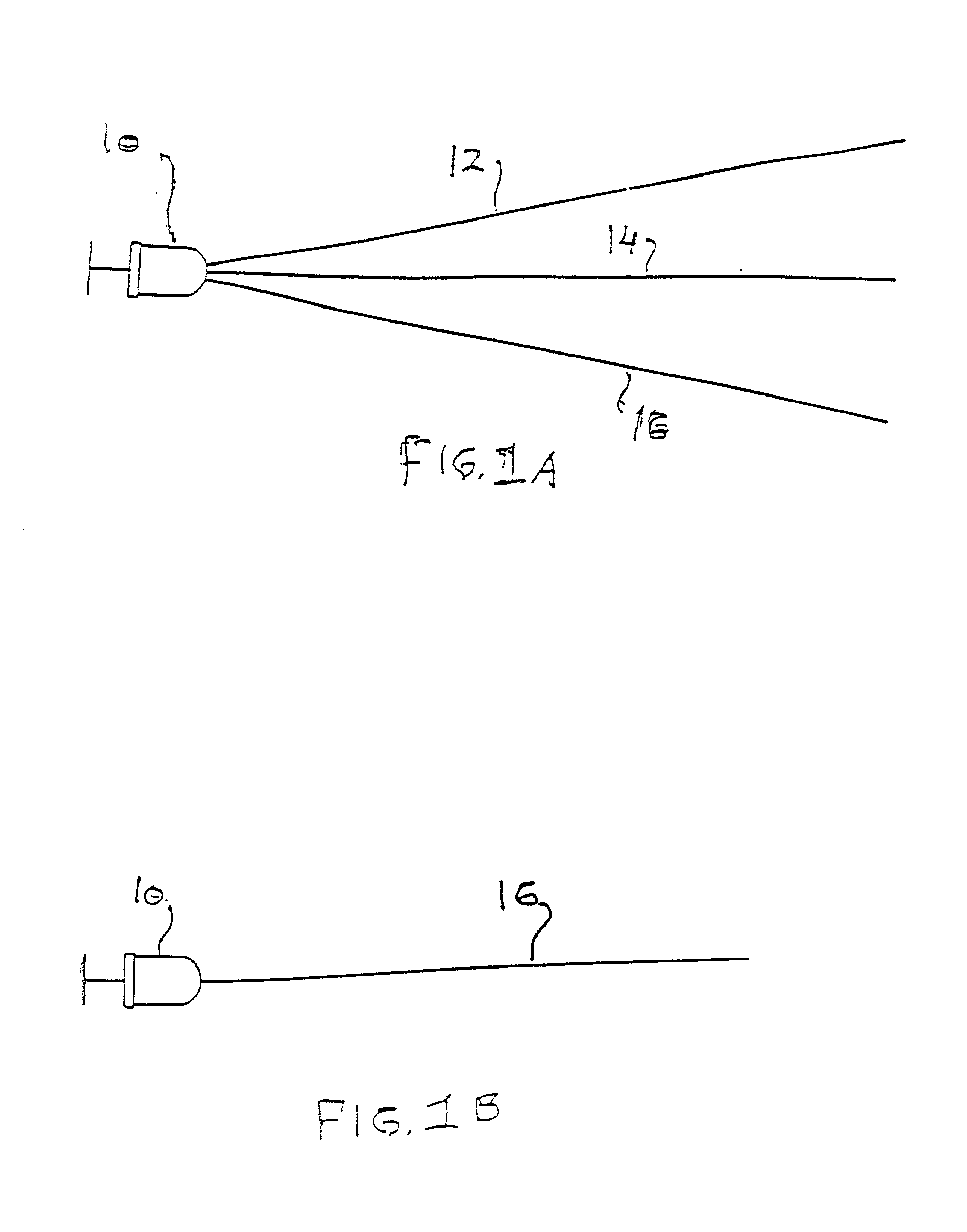
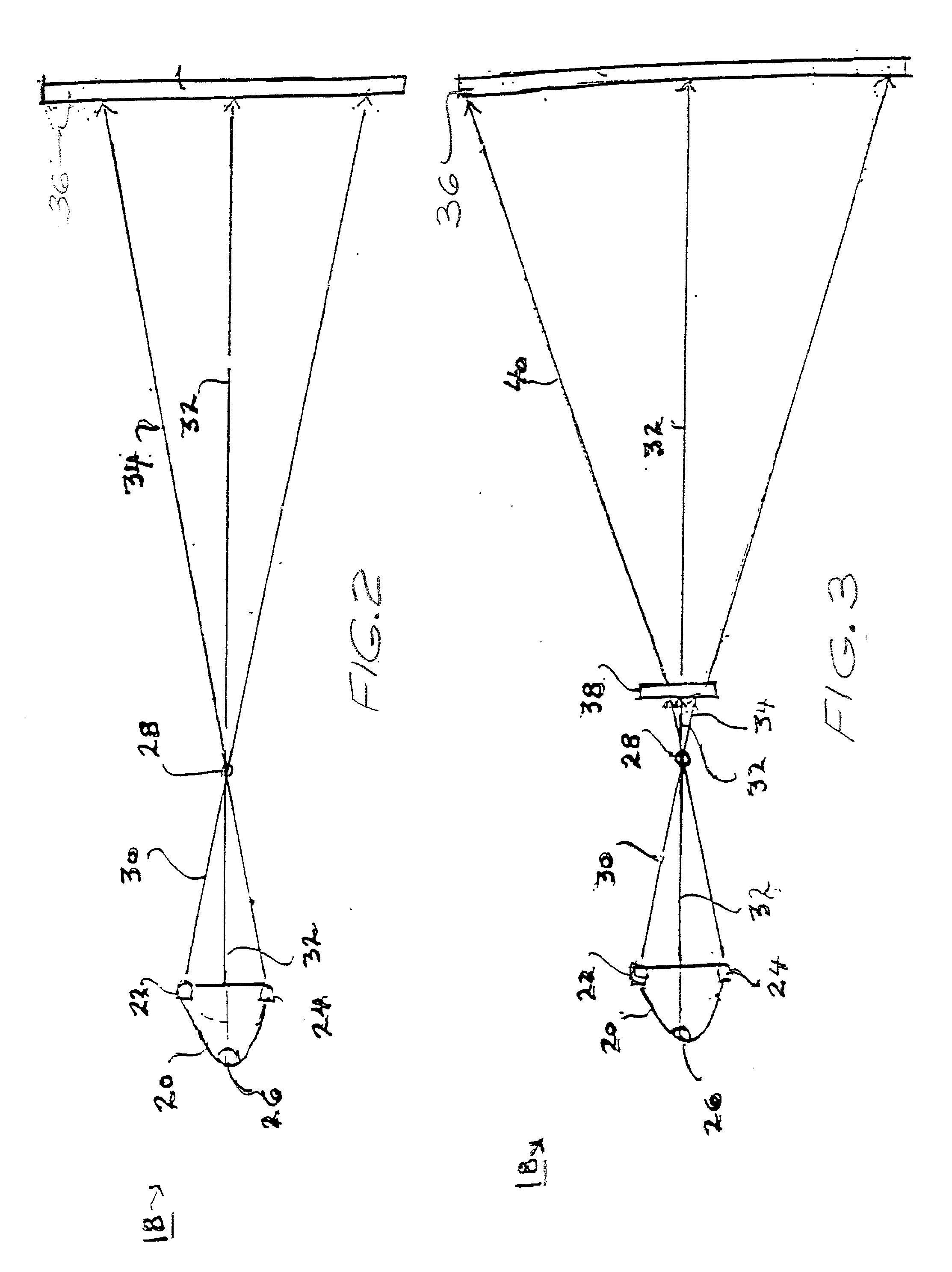
[0127] FIG. 1A shows a typical light emitting diode (LED), or diode, 10 generating a diode beam 12 that comprises a diode central beam 14 and a typical diode beam spread 16 that typically ranges between approximately 50.degree. to 70.degree. in accordance with the specifications of various manufacturers. Most of the diode beam strength and brightness is contained in the course of this application in diode central beam 14 with the understanding that typical slight diode beam spread 16 is included as in FIG. 1B. FIGS. 2-7 show various configurations of an architectural, theatrical, and stage invention with each configuration being schematically represented as follows.

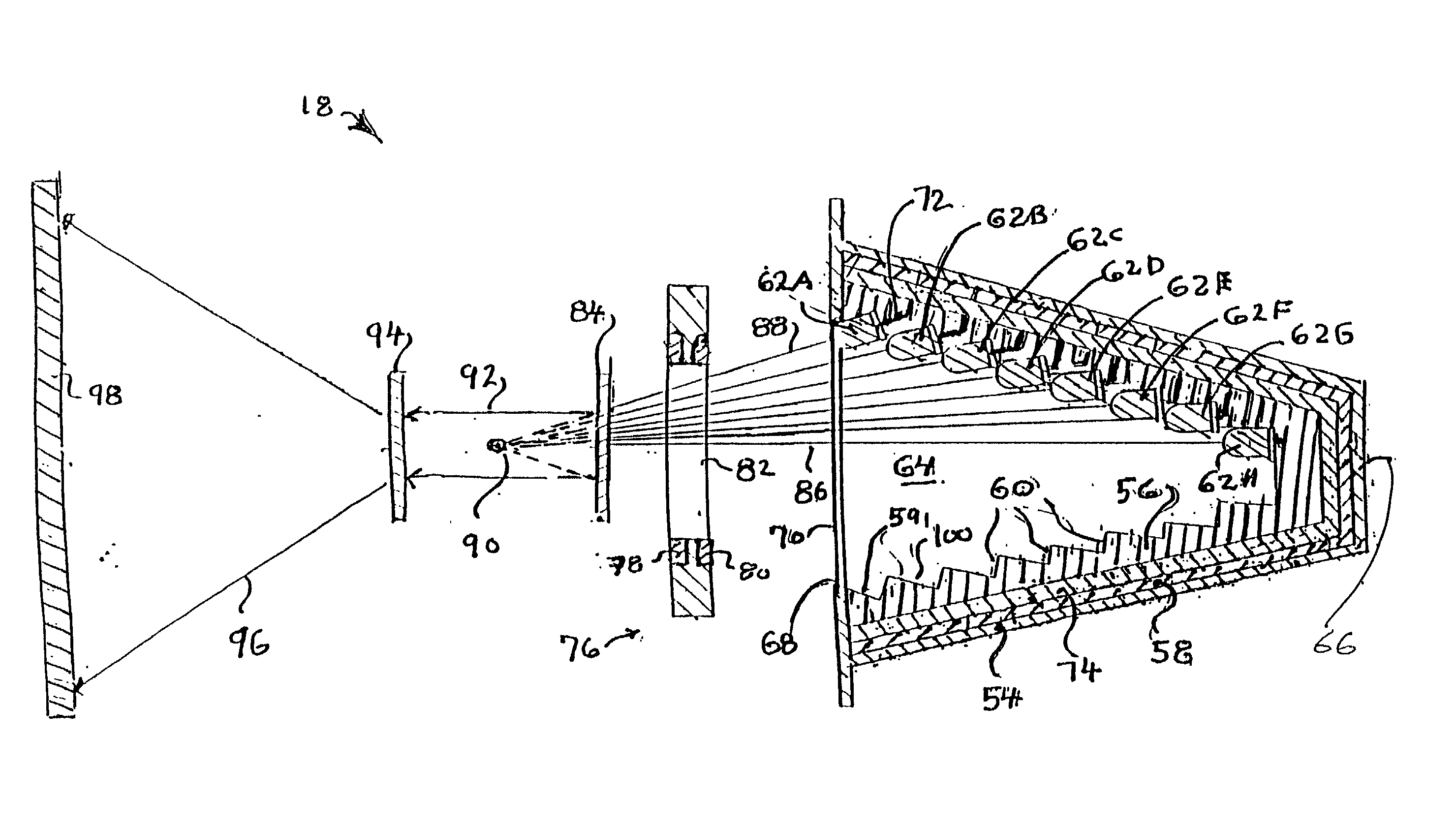
[0128] A basic configuration of the architectural, theatrical, and stage lighting system 18 in accordance with the present invention is shown in...


PUM


Abstract

A lighting system for stage, theatrical and architectural lighting, comprising a frame for supporting a plurality of light emitting diodes. The diodes are mounted to the frame so that each diode is both secured to the frame and also simultaneously positioned wherein each discrete diode light beam is directed to a prescribed remote focal point (target zone) and thereupon directed to a predetermined illumination area. Electrical power for transmitting and controlling electrical voltage to light emitting diodes by electrical circuitry integral with the frame. The frame can be configured as any hollow volume such a cone, a semi-ellipse, and a semi-sphere or can be configured as planar. Flexible blanks having apertures and pads for electrical connections can be used to construct rigid frames. An imaging gate a collimating lens and a focusing lens can be interposed between the frame and the illumination area. The frame can also be a sandwich frame having positive and negative electrically conductive layers interposed between layers of biasable insulating foam.

Description

[0001] The present invention relates to light emitting diode illumination sources used in combination with architectural, theatrical and stage lighting systems.[0002] Incandescent and halogen type lamps have been widely used in various conventional lighting devices for the projection of light onto a surface for illumination and for general illumination purposes. Such lamps depend on the heating of a tungsten wire filament to a high temperature and therefore emit light. These lamps are not energy efficient and they generate excessive heat.[0003] Illuminating light sources such as metal halide arc lamps, gas discharge lamps, fluorescent lamps and halogen light bulbs, as examples, have been widely used in various conventional lighting devices for the projection of light onto a surface for illumination. Such light sources are used in architectural, theatrical and stage lighting systems as well as in industrial applications for lighting surfaces, scenery, an object, or a person. These li...

Claims


Application Information

Patent Timeline
IPC IPC(8): H01R4/24H01R33/09H05K1/18H05K3/30H05K3/32
CPCF21V5/008F21V14/06F21V19/0025F21W2131/406F21Y2101/02F21Y2111/002Y10S362/80H01R4/2404H01R33/09H05K1/189H05K3/303H05K3/326F21Y2113/005F21Y2107/10F21Y2113/13F21Y2115/10H01R4/2406
Inventor LUK, JOHN F.
Owner ALTMAN STAGE LIGHTING
Why Eureka
Try Eureka