Sound source probing system

Inactive Publication Date: 2002-12-05
KUMAGAI GUMI CO LTD +1
View PDF6 Cites 86 Cited by
  • Summary
  • Abstract
  • Description
  • Claims
  • Application Information

AI Technical Summary

Problems solved by technology

However, it is time-consuming and not efficient to locate the source.
Although measurement and analysis take long in the above method making use of the correlation between sound pressure waveforms and the above method making use of acoustic holography, the methods are effective in a limited space but have a problem that a s

Method used


Image

  • Sound source probing system
  • Sound source probing system
  • Sound source probing system

Examples


Example

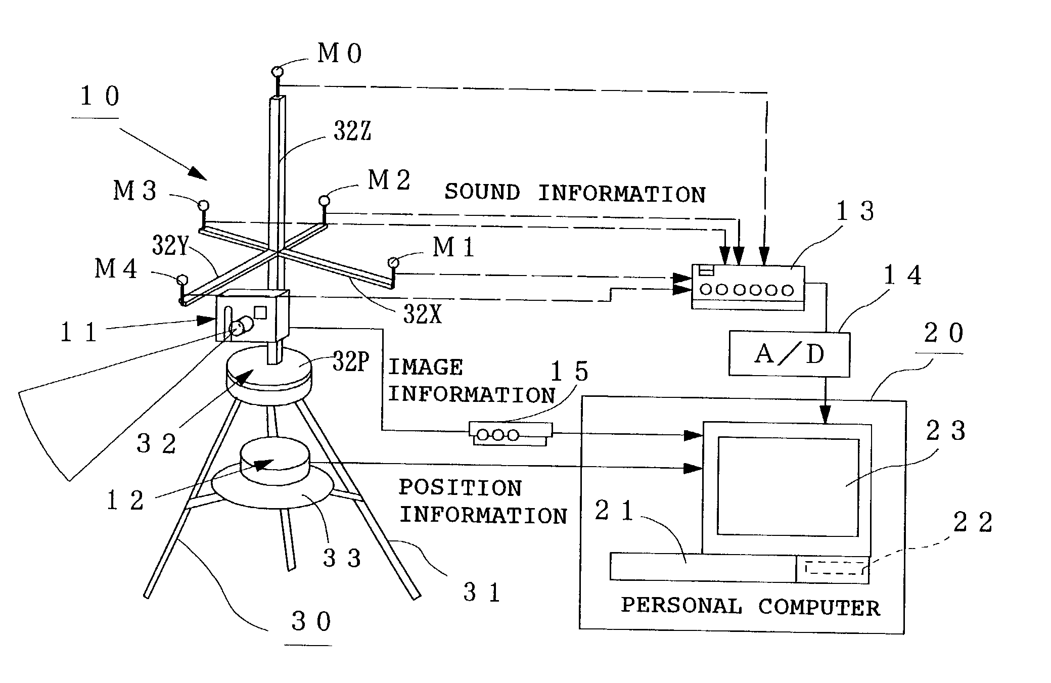
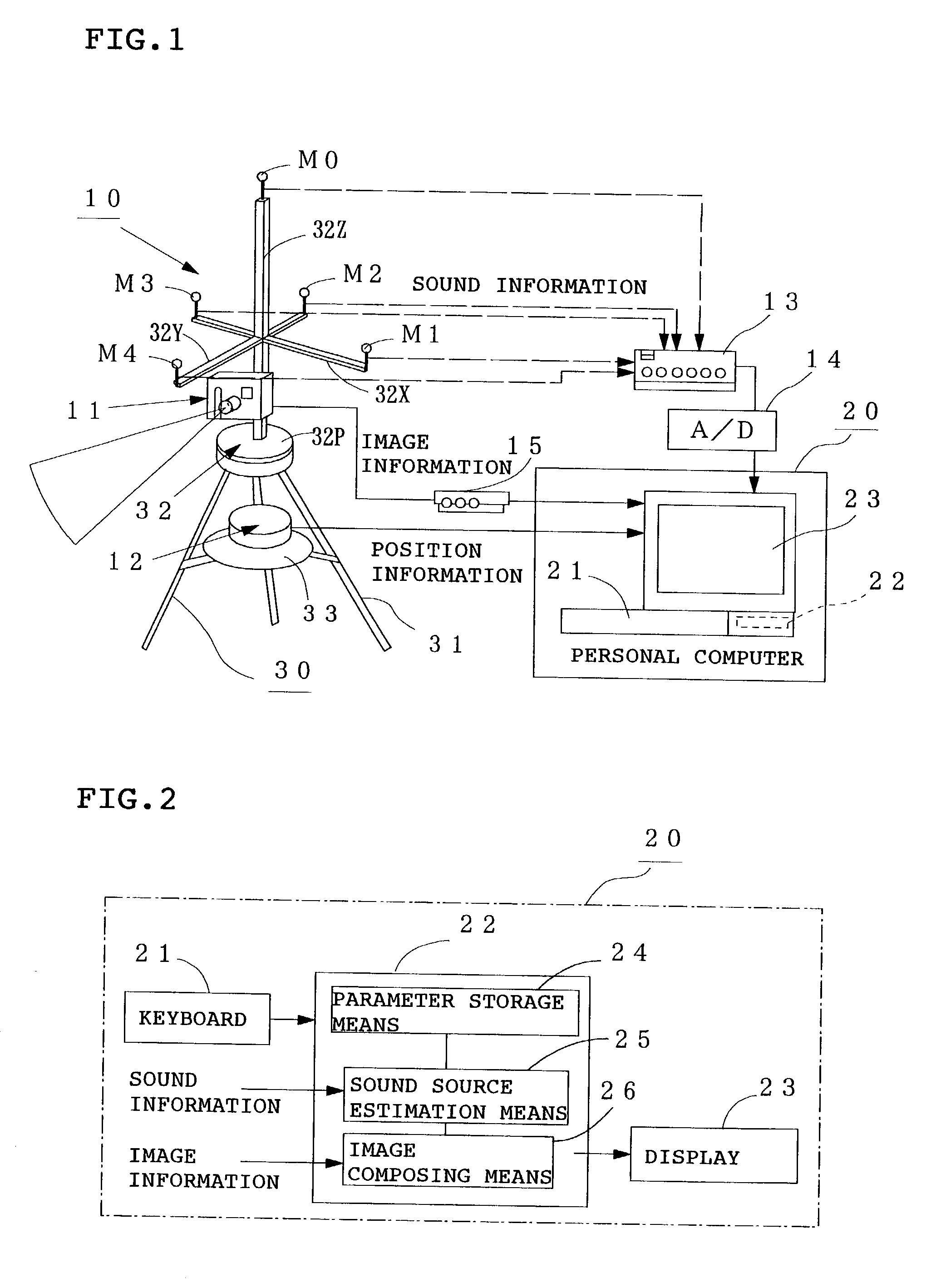
[0033] FIG. 1 is a schematic diagram of a sound source locating system according to Embodiment 1. M1 to M4 are microphones for measuring the sound pressure level of a noise from an unshown sound source, M0 is an auxiliary measuring microphone, 11a CCD camera for picking up an image around the location of the sound source (to be simply referred to as "camera" hereinafter), 12 GPS for specifying the ground positions of the above microphones M0 to M4, 13 amplifier for amplifying sound pressure signals collected by the above microphones M0 to M4, 14 A / D converter for converting the amplified sound pressure signals (analog signals) into digital signals, and 15a video input / output unit for converting the image signal (analog signal) of the camera 11 into a digital signal.

[0034] Denoted by 20 is a personal computer which comprises a keyboard 21 as input means, a storing / computing unit 22 for computing the estimation of the location of the sound source and a display 23 as image display mean...

Example

EMBODIMENT 2

[0064] FIG. 7 is a schematic diagram of a sound source locating system according to Embodiment 2. In this Embodiment, five microphones M1 to M5 arranged in a square columnar form are used to estimate the horizontal angle .theta. and elevation angle .phi. of the sound source. Although other elements are the same as in the above Embodiment 1, in this Embodiment 2, sound information from the above microphones M1 to M5 is used to estimate the location of the sound source by means of the personal computer 20.

[0065] A description is subsequently given of an example of the arrangement of the microphones M1 to M5.

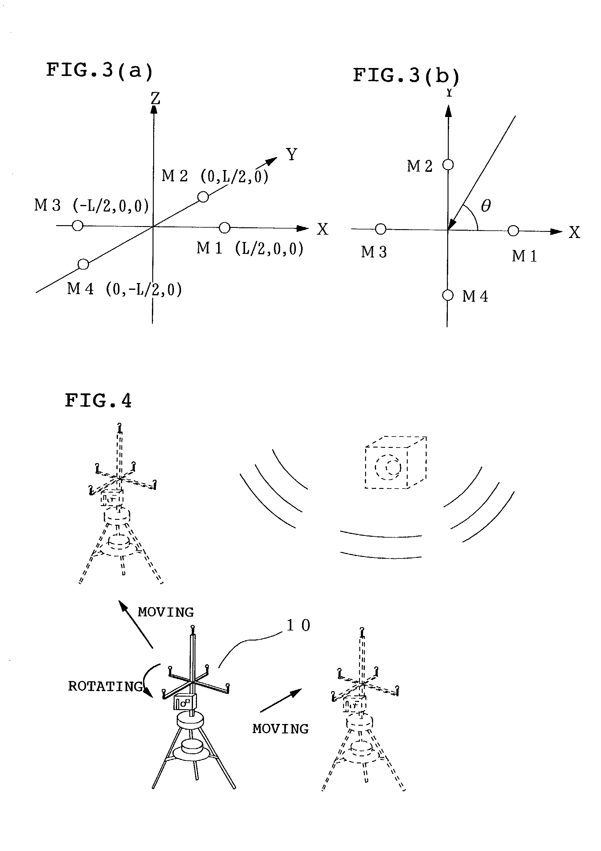
[0066] As shown in FIG. 7 and FIG. 8, the microphones M1 to M4 are disposed above the above rotary frame 32 (in the Z-axis direction) so that their detection portions form a regular square with the origin O on the X-Y plane as the center thereof. Specifically, the detection portions of the microphones M1 and M3 are placed at points (L / 2, 0, 0) and (-L / 2, 0, 0) on the X ...


PUM


Abstract

In order to locate and display the source of a sound such as a noise at a factory or the like accurately even when it is outside, a pair of microphones (M1, M3) and another pair of microphones (M2, M4) are disposed on the X axis and Y axis with a distance L therebetween, respectively, the direction of the sound source is estimated from a difference between sound arrival times to the microphones (M1, M3) and a difference between sound arrival times to the microphones (M2, M4), an image around the estimated location of the sound source is picked up by a camera, and the above estimated location of the sound source is displayed on the above image displayed on the display of a personal computer.

Description

[0001] 1. Field of the Invention[0002] The present invention relates to a sound source locating system for locating the source of a noise and displaying the location of the source to cope with noises at a factory or the like.[0003] 2. Description of the Prior Art[0004] At a factory or the like, many kinds of low-frequency noises having a frequency of 50 Hz to 60 Hz or a frequency double that frequency are generated from a power supply box and a transformer such as a relay. To cope with such noises, an operator measures a sound pressure distribution around a noise generating device with a noise meter to locate the source of the noise and take countermeasures against it. However, it is time-consuming and not efficient to locate the source. Then, a method of estimating the source of a sound such as a noise using an acoustic technique is now under study.[0005] Conventionally proposed sound source locating methods include (1) one making use of the correlation between sound pressure wavef...

Claims


Application Information

Patent Timeline
IPC IPC(8): G01S3/782G01H3/00G01H3/12G01S1/80G01S3/808G01S5/20G01S5/22
CPCG01H3/00G01H3/12G01S5/22G01S5/20G01S3/8083
Inventor SUGIYAMA, TAKESHIWADA, HIROYUKIZAIMA, TAKEFUMIOWAKI, MASANAOYAMASHITA, YASUHIRO
Owner KUMAGAI GUMI CO LTD
Why Eureka
Try Eureka