Gas turbine combustion chambers

a combustion chamber and gas turbine technology, applied in the direction of machines/engines, efficient propulsion technologies, lighting and heating apparatus, etc., can solve the problems of dilution, undesirable orifices, and inability to reduce, so as to improve the temperature behavior of the combustion chamber walls, reduce the drawbacks, and prolong the life

Inactive Publication Date: 2002-12-19
SNECMA MOTEURS SA
View PDF11 Cites 68 Cited by
  • Summary
  • Abstract
  • Description
  • Claims
  • Application Information

AI Technical Summary

Benefits of technology

0010] The present invention thus seeks to mitigate such drawbacks by proposing bushings that are fixed in the air injection holes of the combustion chamber while prov

Problems solved by technology

It is known that piercing multiple perforation orifices in the vicinity of primary combustion air and dilution air injection orifices is undesirable since there is a danger of causing cracks to propagate via said orifices.
Unfortunately, the absence of local cooling in this zone gives rise to the appearance of hot points and temperature gradients which disturb the high temperature behavior of the combustion chamber side walls.
In addition, the impact of the air and fu

Method used


Image

  • Gas turbine combustion chambers
  • Gas turbine combustion chambers
  • Gas turbine combustion chambers

Examples


Embodiment Construction

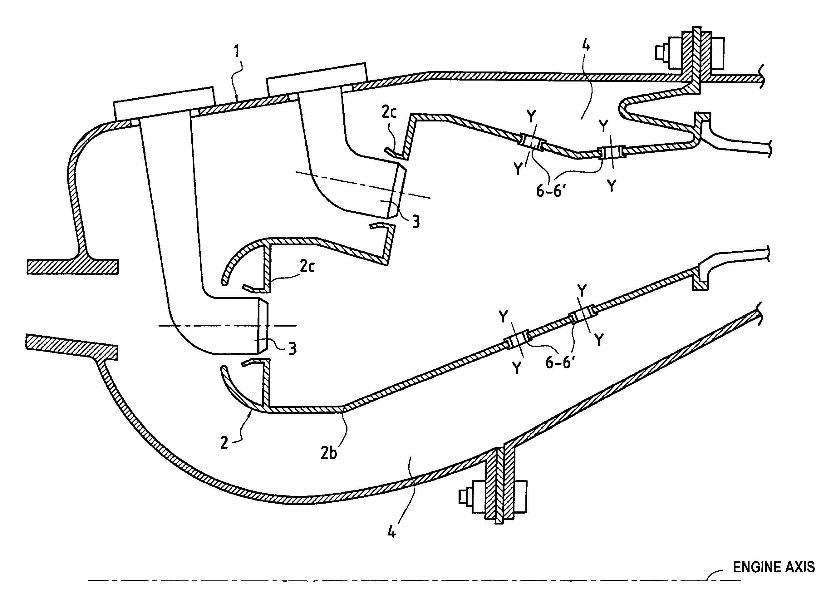
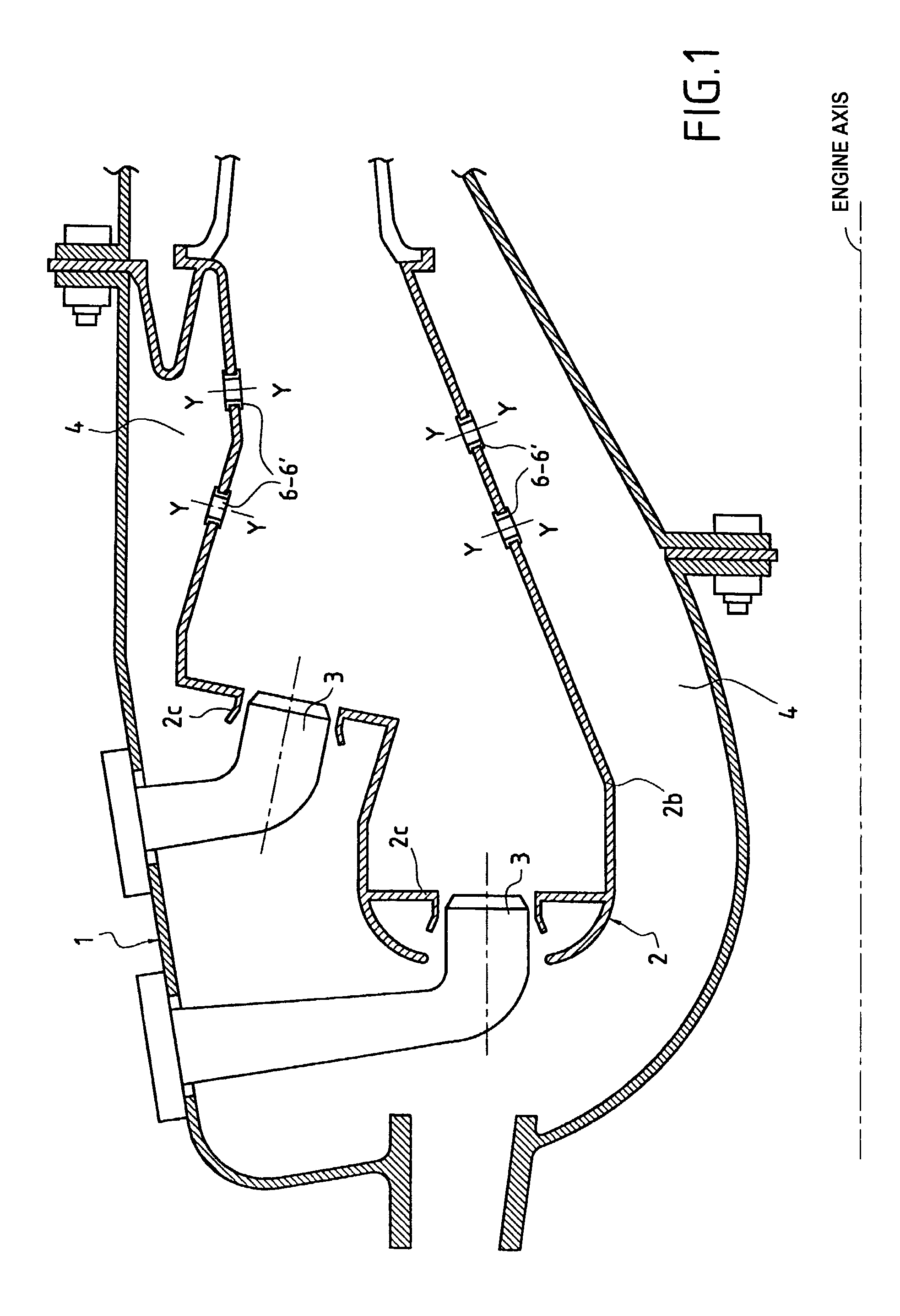
[0019] Reference is made initially to FIG. 1 which is an axial section view of a combustion chamber for an aircraft engine gas turbine.

[0020] Typically, a gas turbine possesses a compression section (not shown) in which air is compressed prior to being introduced into a combustion chamber casing 1, and then into a combustion chamber 2 situated therein. Thereafter the air is mixed with fuel injected into the combustion chamber prior to being burnt therein. The gas generated by this combustion is then directed towards a high pressure turbine (not shown), prior to being exhausted.

[0021] In the embodiment shown in FIG. 1, the combustion chamber 2 is of the annular type. Naturally, the present invention also applies to any other shape of combustion chamber.

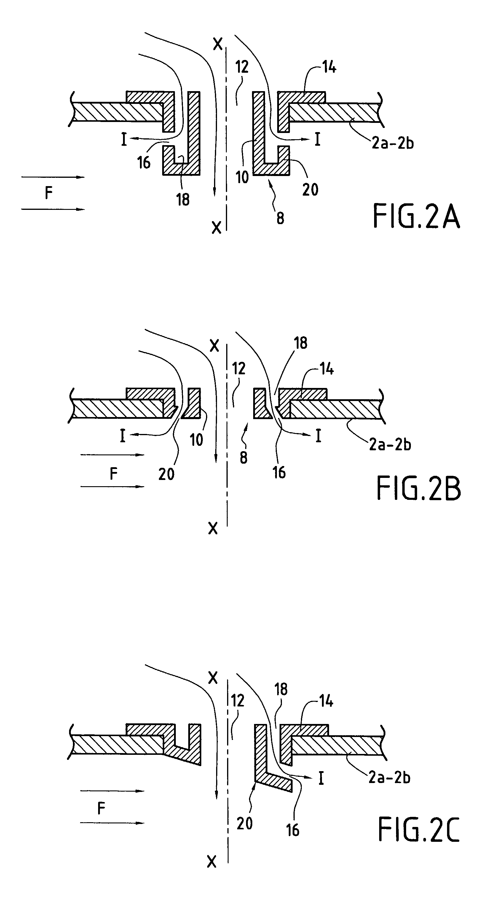
[0022] The combustion chamber 2 is defined by outer and inner side walls 2a and 2b interconnected by an end wall 2c fitted with injector systems 3 through which fuel is introduced into the combustion chamber. Conventionally, such injec...


PUM


Abstract

A combustion chamber for a gas turbine made up of outer and inner side walls, the combustion chamber being received in a casing so as to define an annular space between the combustion chamber and the casing in which there flows air for combustion, for dilution, and for cooling the combustion chamber, the side walls of the combustion chamber being pierced by a plurality of holes in which bushings of substantially elliptical right section are fixed to define air injection passages for injecting air into the combustion chamber, each bushing having a peripheral wall in which at least one additional orifice is formed opening out into the combustion chamber in the immediate vicinity of the side wall of the combustion chamber in which said bushing is fixed so that the air passing through said orifice flows substantially along said peripheral wall, the peripheral wall of each bushing having at least one groove opening out into the annular space and into which the or each orifice opens out so as to be fed with air and so as to cool the peripheral wall of the bushing.

Description

[0001] The present invention relates to the field of combustion chambers for airplane gas turbine engines, and more particularly to combustion chambers having air injection orifices through their walls.[0002] A combustion chamber for a gas turbine is disposed in conventional manner inside a housing that constitutes a casing. It is made up of inner and outer side walls that are united by an end wall on which injector systems are mounted that are distributed over one or more heads.[0003] Conventionally, the air coming from the high pressure compressor of the turbine is admitted into the combustion chamber. A fraction of this air feeds the combustion zone axially via end wall injector systems and another fraction enters transversely via primary air injection holes pierced through the inner and outer side walls of the combustion chamber. A further fraction of this air, referred to as a "dilution" fraction, is also introduced transversely, but further downstream within the combustion cha...

Claims


Application Information

Patent Timeline
IPC IPC(8): F23R3/04
CPCY02T50/675F23R3/045Y02T50/60
Inventor DAVID, ETIENNEDURET, JEAN-MICHELHERNANDEZ, DIDIERSANDELIS, DENISWLOCZYSIAK, ALAIN
Owner SNECMA MOTEURS SA
Why Eureka
Try Eureka