Fiber-reinforced composite springs

a composite spring and fiber reinforcement technology, applied in the field of fiber reinforcement composite springs, can solve the problems of increasing fatigue life and achieve the effect of increasing fatigue life and predicting load versus deformation behavior

Inactive Publication Date: 2002-12-19
THE UNIVERSITY OF AKRON
View PDF0 Cites 55 Cited by
  • Summary
  • Abstract
  • Description
  • Claims
  • Application Information

AI Technical Summary

Benefits of technology

[0006] Advantageously, the fiber-reinforced composite springs of this invention can have circular or non-circular wire cross-sections, and they exhibit predictable load versus deformation behavior. Also, they exhibit increased fatigue life due to the absence of any surface irregularities. Also, the process of this invention advantageously allows one to produce composite springs that have a smooth surface, which is comprised of a continuous polymer layer having a desired thickness.

Problems solved by technology

Also, they exhibit increased fatigue life due to the absence of any surface irregularities.

Method used


Image

  • Fiber-reinforced composite springs
  • Fiber-reinforced composite springs
  • Fiber-reinforced composite springs

Examples


Embodiment Construction

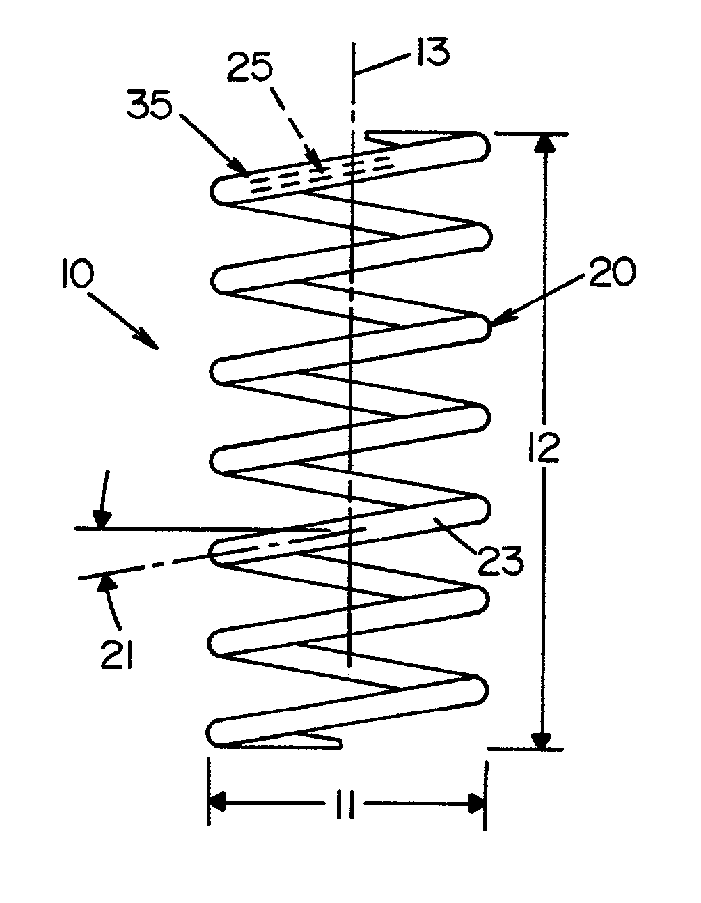
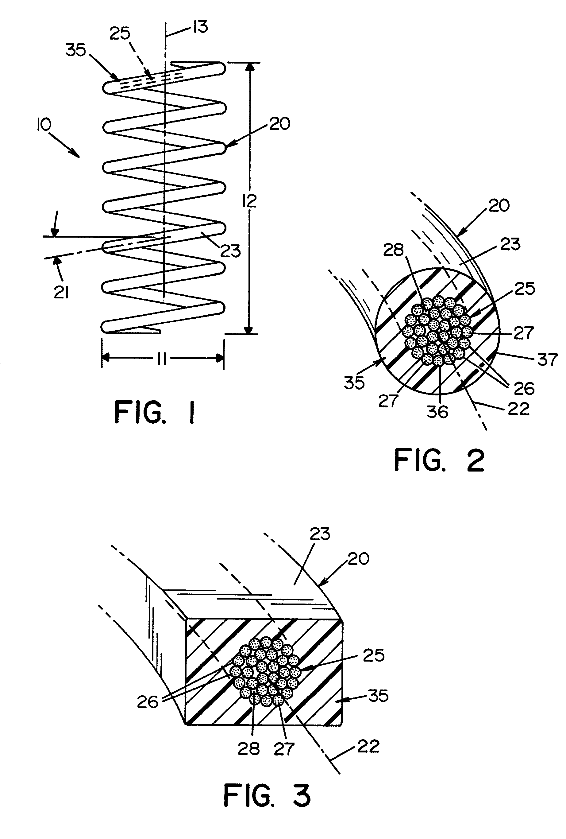
[0013] The fiber-reinforced composite spring of this invention is shown in FIG. 1. Spring 10 includes a coiled spring wire 20, which is coiled at a helix angle 21. The cross-section of spring wire 20 is shown in FIGS. 2 and 3, where fiber-reinforced core 25 and an outer layer 35 are shown.

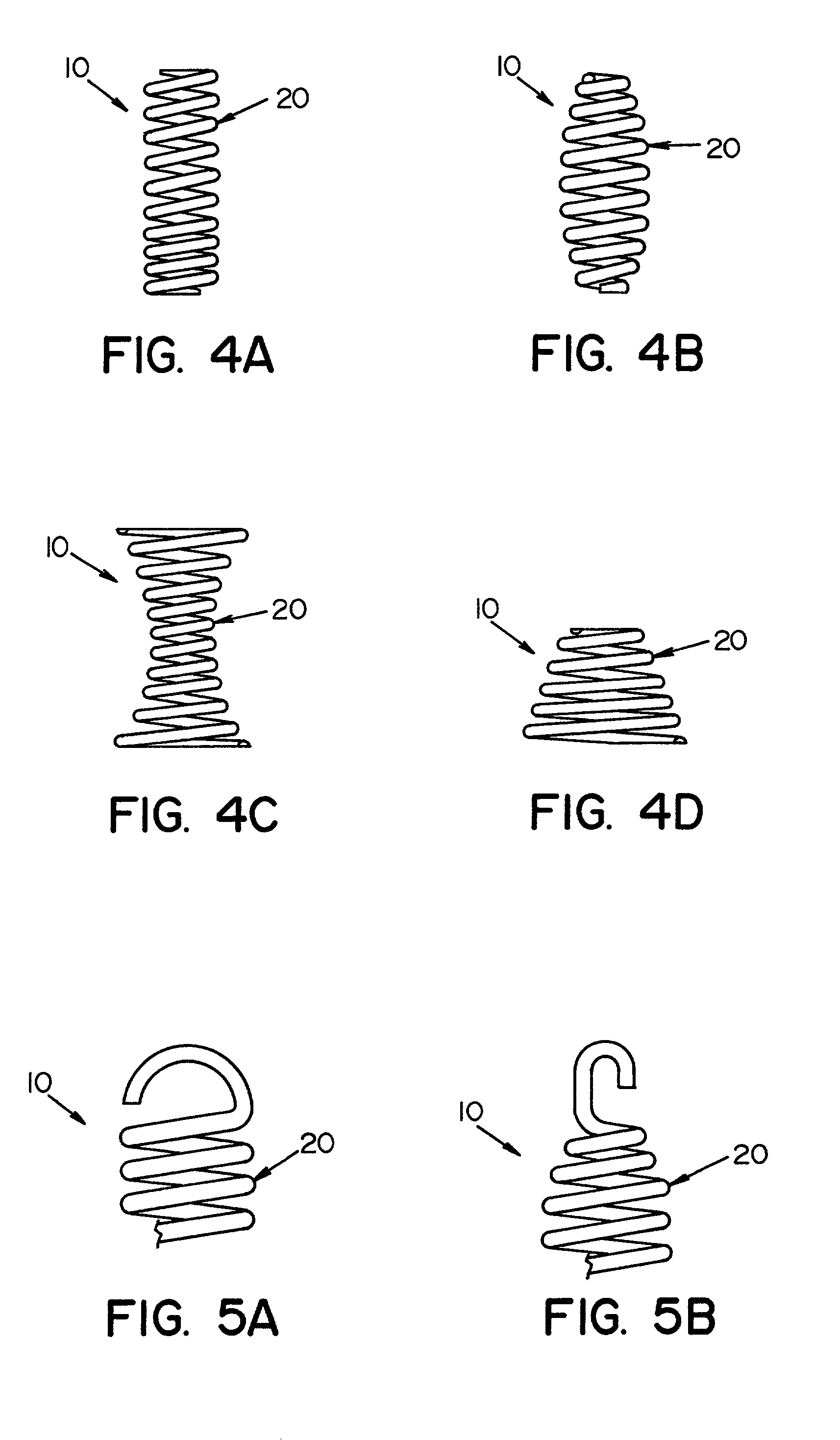
[0014] With reference to FIG. 1, spring 20 has a coil diameter 11 and a length 12. Both coil diameter 11 and length 12 can vary based upon the desired application. Likewise, helix angle 21 can vary based upon the desired application. Varying helix angle 21 within the same spring will result in a variable rate spring as shown in FIG. 4A.

[0015] Also, coil diameter 11 can vary along the longitudinal axis 13 of spring 10. For example, if the coil diameter decreases towards both ends of the spring, a barrel will be formed as shown in FIG. 4B. If the coil diameter increases towards both ends of the spring, an hourglass spring will be formed as shown in FIG. 4C. If the coil diameter increases toward one e...


PUM

PropertyMeasurementUnit
winding angleaaaaaaaaaa
speedsaaaaaaaaaa
speedsaaaaaaaaaa

Abstract

A fiber-reinforced composite spring comprising a coiled spring wire that comprises a fiber-reinforced core having longitudinal axis, where the core comprises core-reinforcing fiber tows that are twisted about the longitudinal axis of the core, and an outer layer surrounding the fiber-reinforced core, where the outer layer comprises a resin that is devoid of fiber tows.

Description

[0001] This invention relates to fiber-reinforced composite springs and methods for making the same.[0002] Composite springs are known. The method of manufacturing these springs has a major influence on their final properties. Traditionally, composite springs have been made by impregnating fiber yarns, such as glass or carbon yarns, with a suitable resin. The impregnated fibers are then carefully wrapped with a water-soluble tape such as a polyvinyl alcohol tape. The wrapped fibers are then placed onto a grooved mandrel and cured at elevated temperatures. The wrapping tape is then removed by soaking the final product in water. This process, however, is tedious and labor intensive, and results in an inferior composite spring because the spring surface is not smooth; it contains a spiral pattern created by the presence of the polyvinyl alcohol tape. This pattern affects the deformational performance of the spring, which results in an unpredictable load versus deformation behavior. As ...

Claims


Application Information

Patent Timeline
Patent Type & Authority Applications(United States)
IPC IPC(8): B29C53/12B29C53/14B29C70/54F16F1/366
CPCB29C53/12B29C53/14F16F2224/0241B29L2031/7742F16F1/366B29C70/542
Inventor SANCAKTAR, EROLGOWRISHANKAR, SUNIL
Owner THE UNIVERSITY OF AKRON
Why Eureka
Try Eureka