
Hybrid inflator

Inactive Publication Date: 2002-12-19
DAICEL CHEM IND LTD
View PDF2 Cites 13 Cited by
  • Summary
  • Abstract
  • Description
  • Claims
  • Application Information

AI Technical Summary

Benefits of technology

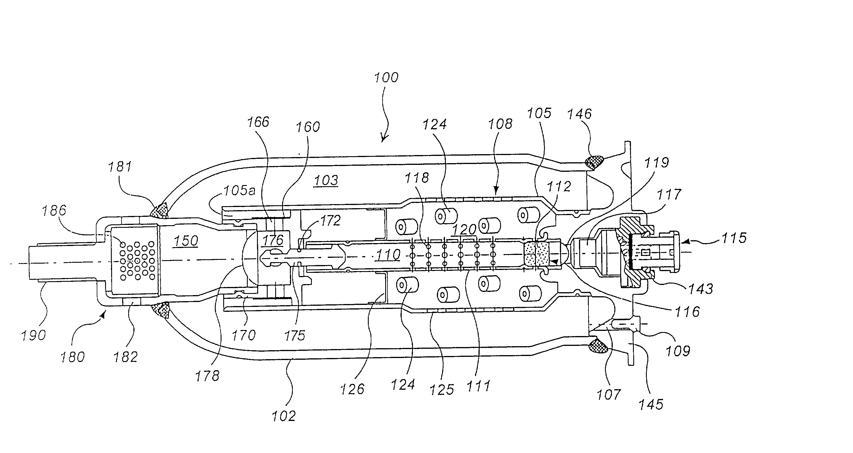
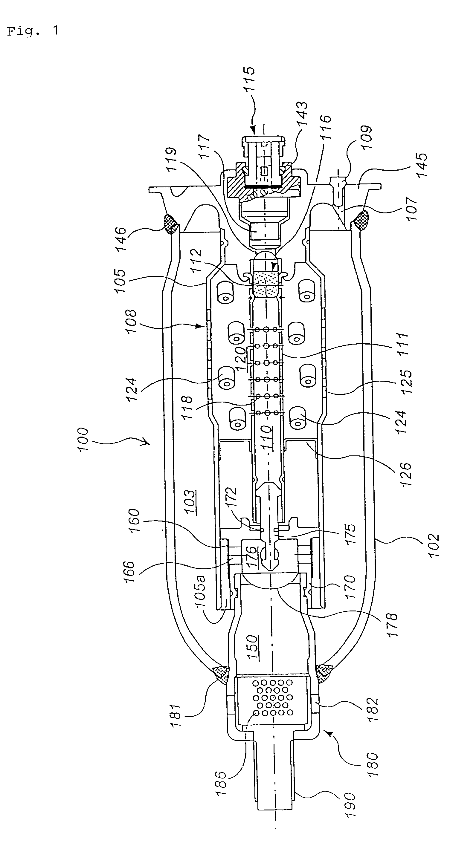
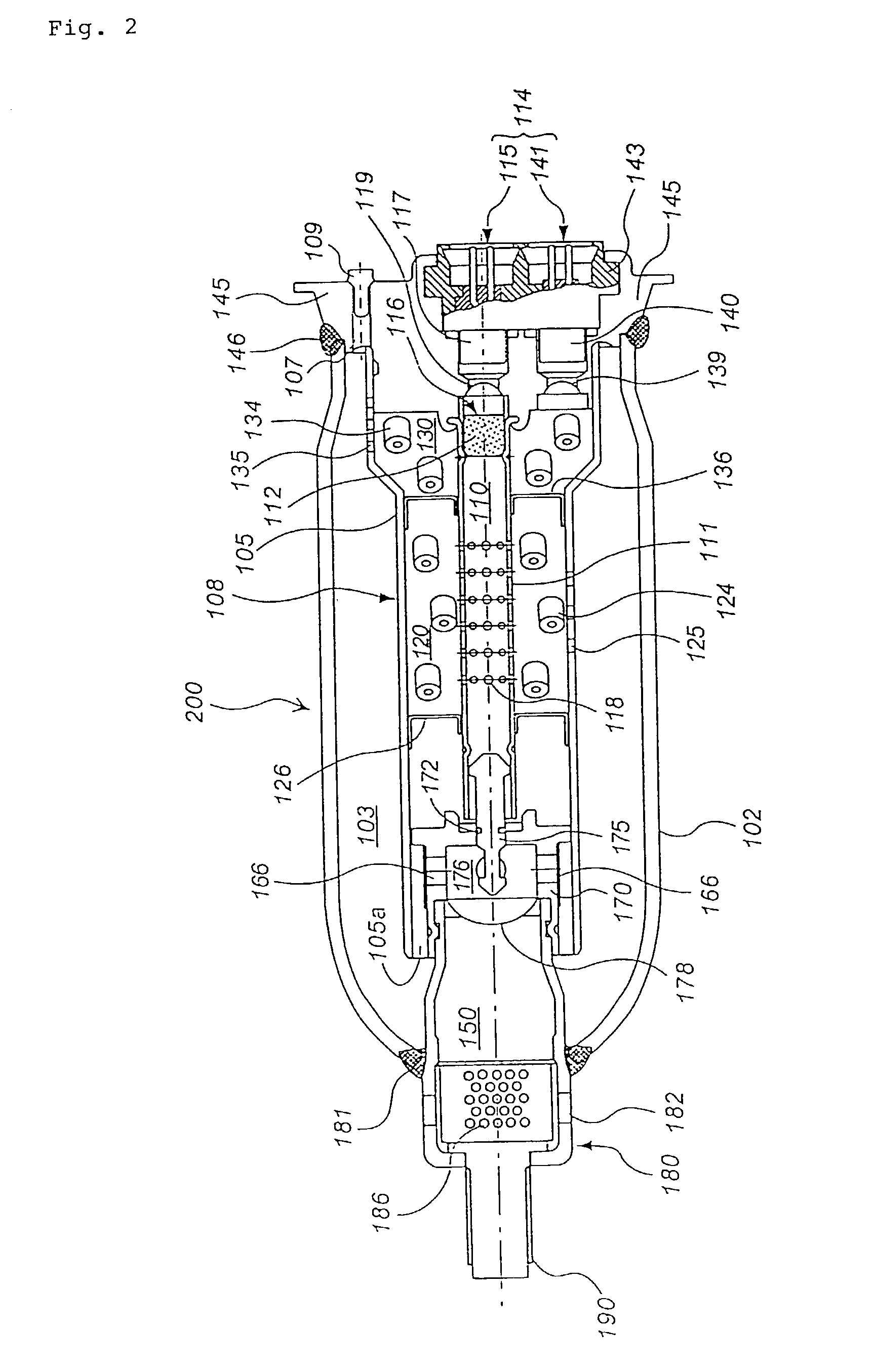
[0005] Incidentally, in the present invention, the passage through which the pressurized medium flows at the time of activation of the hybrid inflator can be set properly or modified according to the structure of the hybrid inflator.
[0006] The present invention is structured such that a change in an internal pressure inside the hybrid inflator is controlled by controlling the amount of outflow of the pressurized medium and the combustion gas according to function of a plurality of the nozzles provided at the passage through which the pressurized medium flows, and in case that the present invention is applied to an air bag system, the air bag can be inflated rapidly and reliably without influence of an environmental temperature in practical use.
[0017] Thus, by adjusting the opening areas of a plurality of the nozzles or the total area thereof, control on the amount of outflow of the pressurized medium and the combustion gas and control on the change in the internal pressure of the hybrid inflator can be performed more easily.
[0020] By changing the pressure required to rupture the shielding means variously, rupturing easiness (i.e., long / short in rupturing time) of the shielding means can be changed in a group of nozzles, so that the amount of outflow of the pressurized medium and the combustion gas can be controlled.

Problems solved by technology

If the gas generating means is deteriorated by the pressure, there is a possibility such that the gas generating means may be smashed easily at combustion.

Method used


Image

  • Hybrid inflator
  • Hybrid inflator
  • Hybrid inflator

Examples


example 1

[0083] A single-type hybrid inflator 100 shown in FIG. 1 was produced. The totally five nozzles 166 (the total opening area A=80.8 mm.sup.2) including two nozzles with a diameter of 5 mm and three nozzles with a diameter of 4.2 mm were provided on the side surface of the adapter 170. Two nozzles with a diameter of 5 mm and one nozzle with a diameter of 4.2 mm among the total nozzles 166 are open (the total opening area of 53.1 mm.sup.2), while two nozzles with a diameter of 4.2 mm are completely closed from the outside with a stainless tape (thickness of 40 .mu.m) (the total opening area of 27.7 mm.sup.2). Incidentally, the other conditions are as follows:

[0084] Pressurized medium: 2.6 mol (10 g) of a mixed gas of argon and helium [Ar: He=96:4 (molar ratio)] (the charging internal pressure of 32,000 kPa) Gas generating agent: 40 g (nitroguanidine:strontium nitrate:carboxymethyl cellulose:Japanes acid clay=34:50:9:7; a single-perforated cylindrical shape having an outer diameter of 5...


PUM


Abstract

The present invention provides a hybrid inflator which easily controls the amount of outflow of a pressurized medium or the like is provided. Part of a plurality of nozzles 166 positioned in a flow-passage of a pressurized medium or the like are closed by a tape 160 to be ruptured due to increase of an internal pressure. When the internal pressure is low, the tape 160 is not ruptured, but when the internal pressure is high, the tape 160 is ruptured. Therefore, the opening area of the nozzles 166 are changed in accordance with the change in internal pressure so that the amount of the outflow of the pressurized medium and the like can be controlled.

Description

TECHNICAL FIELD TO WHICH THE INVENTION BELONGS[0001] The present invention relates to an inflating-type safety system for a motor vehicle, more specifically to a hybrid inflator capable of inflating an air bag rapidly and reliably regardless of an environmental temperature in a practical use and to an air bag apparatus using the hybrid inflator.PRIOR ART[0002] With the development of an inflator for an inflating-type safety system of motor vehicles, a hybrid inflator using both a pressurized gas and a solid gas generating agent has been attracting attention. A main design requirement for a hybrid inflator is that the inflator inflates an air bag to a predetermined amount in a predetermined time so that the air bag is effectively activated. Various proposals concerning a structure to meet the requirement have heretofore been made, where the art disclosed in JP-A No. 7-98814, JP-A No. 10-100851 and the like have been known as the prior arts.[0003] An object of the present invention is...

Claims


Application Information

Patent Timeline
IPC IPC(8): B01J7/00B60R21/26B60R21/272
CPCB60R21/272B60R21/261
Inventor YAMAZAKI, MASAYUKI
Owner DAICEL CHEM IND LTD
Learn More