
Compensation apparatus and method utilising sampled bragg gratings

a sampling apparatus and sample technology, applied in the direction of optical waveguide light guide, instruments, optics, etc., can solve the problems of inability to minimise the problem of dispersion, the broad band dispersion compensating module based on the dispersion compensating fibre cannot provide sufficient accuracy to compensate all channels in a wdm system simultaneously

Inactive Publication Date: 2002-12-19
RPX CLEARINGHOUSE
View PDF0 Cites 49 Cited by
  • Summary
  • Abstract
  • Description
  • Claims
  • Application Information

AI Technical Summary

Problems solved by technology

The problem presented by dispersion increases rapidly with increasing bit rate.
In a WDM digital transmission system, it is not practical to minimise the problems of dispersion by choosing to employ a transmission medium exhibiting near-zero first order dispersive power because low first order dispersive power is associated with aggravated non-linear (e.g. four-wave mixing) distortion.
However, broad band dispersion compensating modules based on dispersion compensating fibre cannot provide sufficient accuracy to compensate all channels in a WDM system simultaneously.
However, it is difficult to manufacture very long fibre Bragg gratings (>1 m) required for broadband compensation (i.e. for dispersion compensation across the entire band occupied by signals in a WDM system.
The known methods based on straining or temperature tuning of silica-based waveguides are in use but have a limited range.
Etalon-based devices have also been used for dispersion compensation purposes, but have insufficient dispersion and slope uniformity within the information bandwidth to be applicable in high spectral density, high bit rate WDM systems.

Method used


Image

  • Compensation apparatus and method utilising sampled bragg gratings
  • Compensation apparatus and method utilising sampled bragg gratings
  • Compensation apparatus and method utilising sampled bragg gratings

Examples


Embodiment Construction

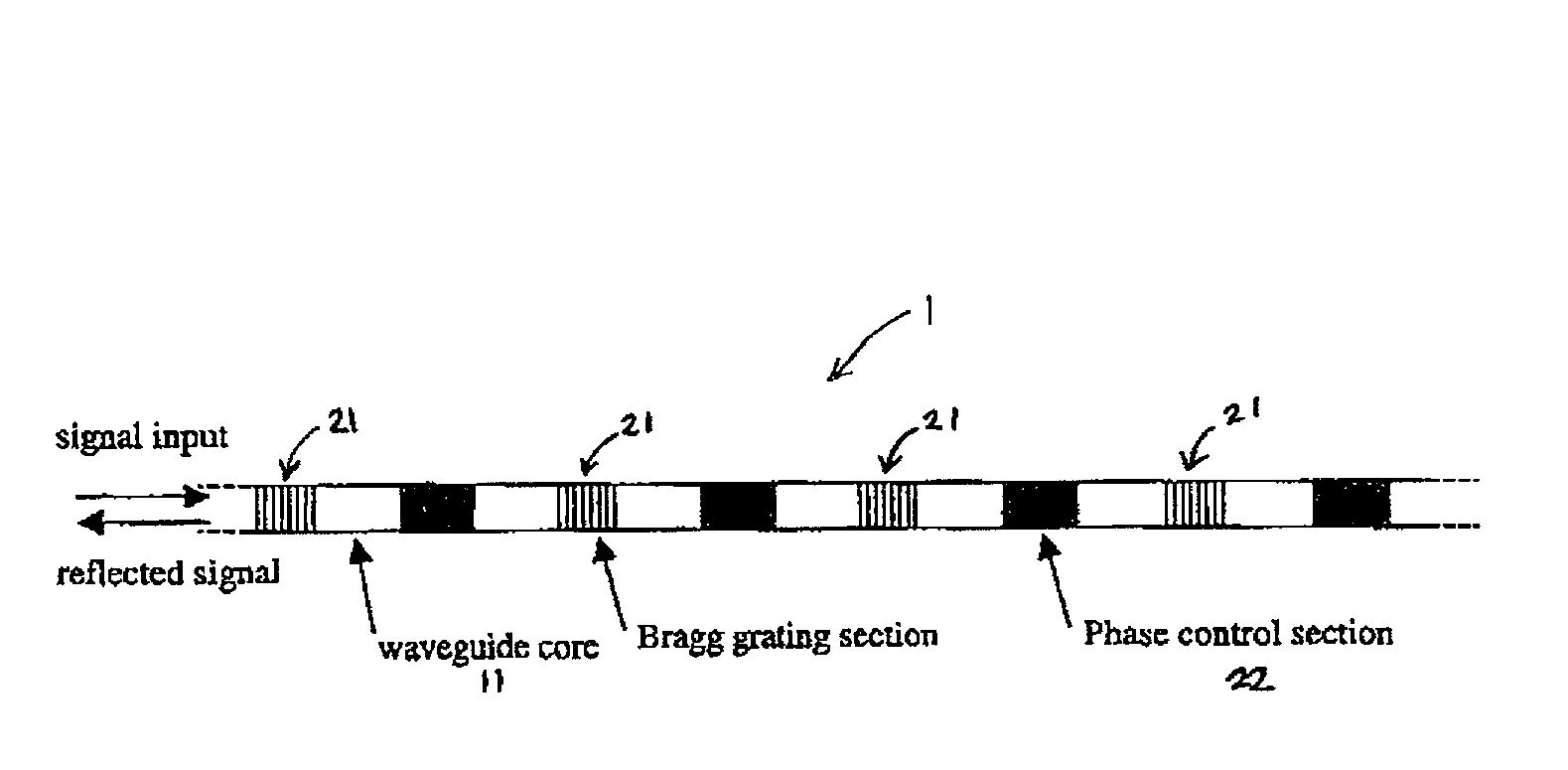
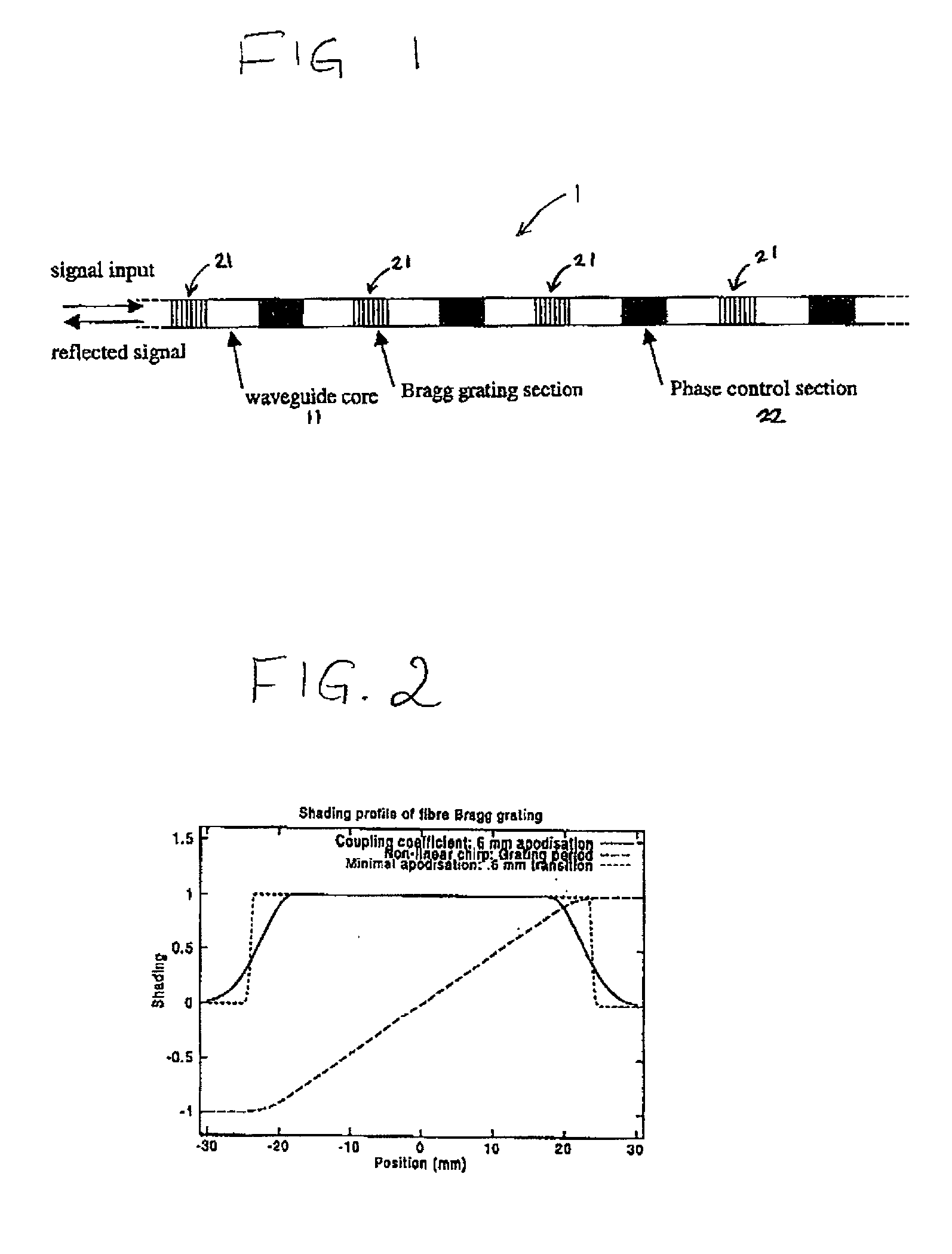
[0074] FIG. 1 shows a section of a waveguide 1 embodying the invention, which preferably is single moded at wavelength of operation. At regular intervals along the waveguide, the effective index of the guide is modulated to form a Bragg grating. The modulation may be achieved by a varying the refractive index of the core, the refractive index of the cladding, the core transverse dimensions or the shape of the core cross-section. The sampled Bragg grating comprises a sequence of grating sections (samples) 21 spaced out at substantially regular intervals along the waveguide core 11.

[0075] In a preferred implementation, regions of high refractive index material are embedded in either or both of the core or cladding of the waveguide. The strength of each of the grating sections 21 is varied by adjusting the refractive index, volume or shape of the deposited material. It may be advantageous to apply a smooth variation in grating pitch along the device.

[0076] The waveguide also contains s...


PUM


Abstract

Dispersion compensation devices are described which comprise waveguides including sampled Bragg gratings which exhibit comb-like reflectance characteristics. The profile of effective refractive index along the length of the grating is controlled to adjust the position of the teeth and / or to control the dispersion exhibited by the device (i.e. to control the chirp of the grating). The devices can thus be used to provide dispersion compensation to any one of a number of wavelength channels in a WDM system. In preferred arrangements, the effective refractive index distribution is set by a applying a temperature distribution along the length of the grating, or by setting an applied electric field.

Description

[0001] This invention relates to the compensation of chromatic dispersion, hereinafter referred to as dispersion, in optical transmission systems. In particular, although not exclusively, this invention relates to the compensation of dispersion in Wavelength Division Multiplexed (WDM) optical communications systems.BACKGROUND TO THE INVENTION[0002] Generally, chromatic dispersion is the dependence of wave velocity on wavelength as a wave travels through a medium. In the field of optical communications, chromatic dispersion is used to refer to the dependence of group delay, .tau., on wavelength, .lambda..[0003] Linear (first order) dispersion, D, is the measure of the rate of change of group delay, .tau., with wavelength .lambda.. (D=d.tau. / d.lambda.). Linear dispersion is typically measured in picoseconds per nanometre (ps / nm). In the case of a transmission medium, for instance, an optical fibre waveguide, whose waveguiding properties are uniform along its length, the linear dispers...

Claims


Application Information

Patent Timeline
Patent Type & Authority Applications(United States)
IPC IPC(8): G02B6/12G02B6/34
CPCG02B6/02085G02B6/02195G02B6/02204G02B2006/12107G02B6/29322G02B6/29394G02B6/12007
Inventor ROBINSON, ALANCLAPP, TERRY V.
Owner RPX CLEARINGHOUSE
Learn More