Electric outlet with rotatable receptacles
- Summary
- Abstract
- Description
- Claims
- Application Information
AI Technical Summary
Benefits of technology
Problems solved by technology
Method used
Image
Examples
second embodiment
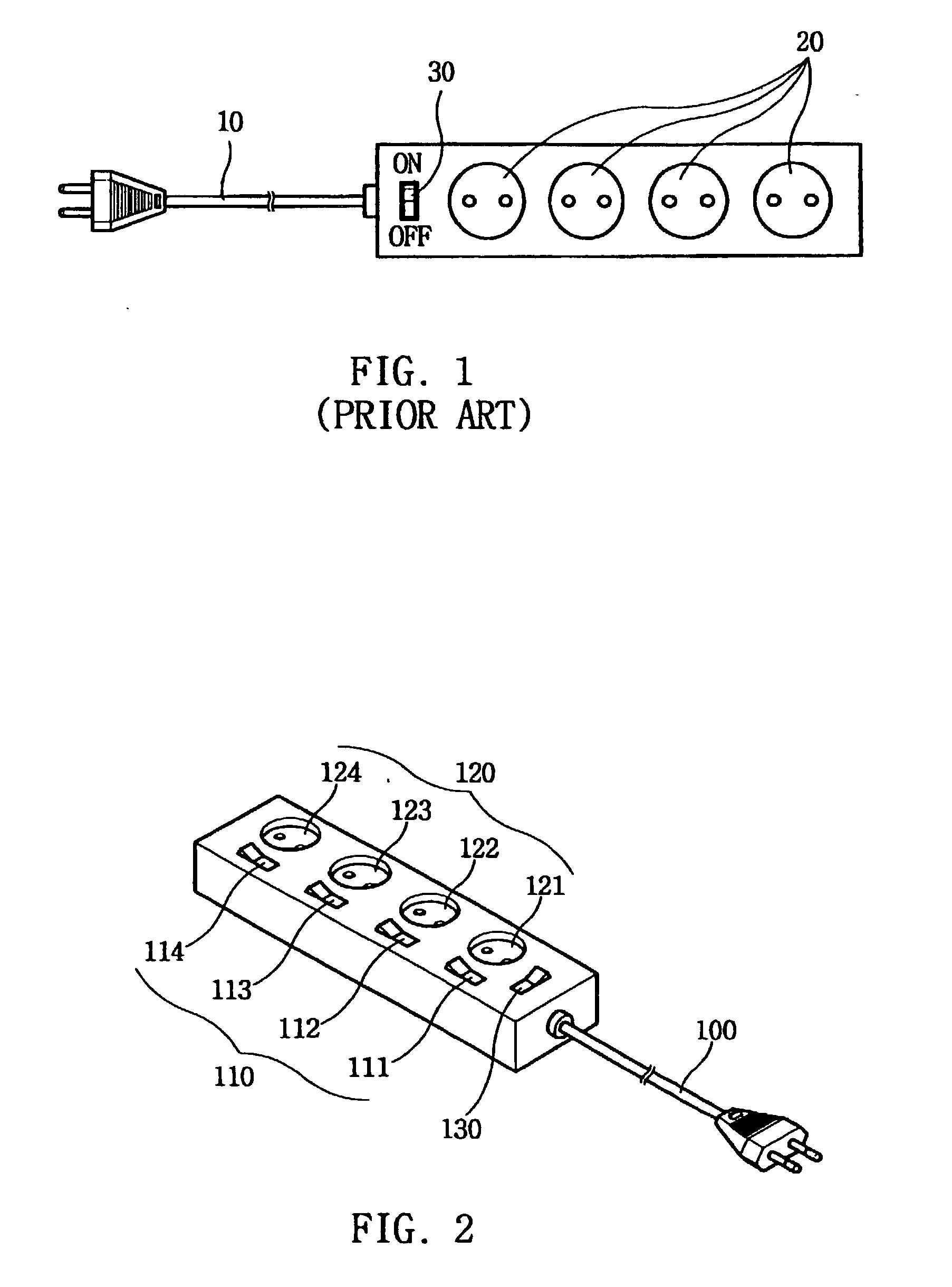
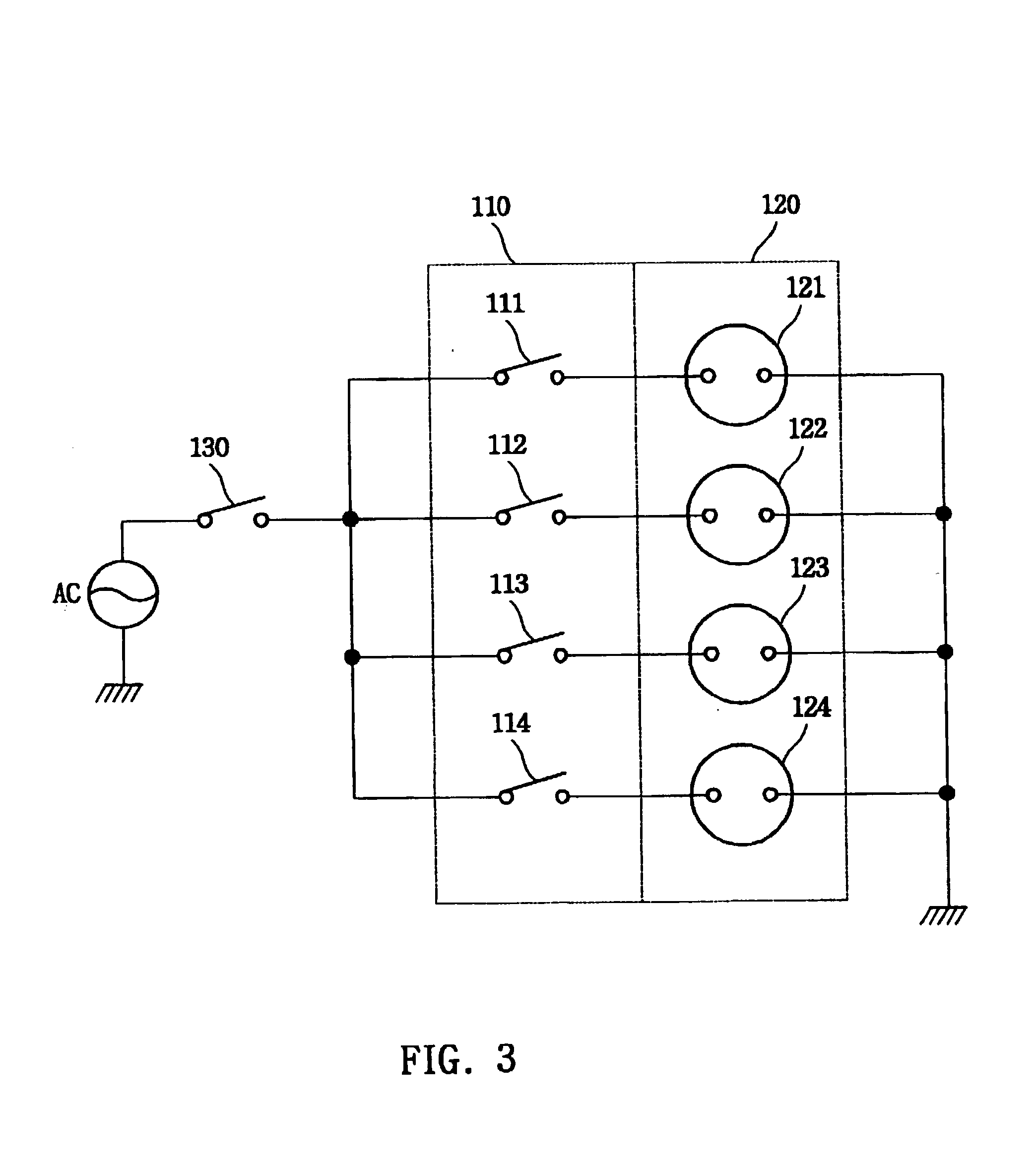
[0077] the present invention will be explained with reference to FIG. 4 and FIG. 5. FIG. 4 is a schematic drawing illustrating the power-control apparatus. As shown in the drawing, a switch box 210 is integrally formed a plurality of individual switches 221.about.225 in a switch unit 220 for separately supplying the power from the power source to a remote plug unit 260. [The] Remote plug unit 260 is formed by a plurality of individual remote plugs 261.about.266 which each connect to extension cord 250. A main switch 230 is provided between the power supply cord 200 and the individual switches 221.about.225 of the switch unit 220. A timer 240 for setting operation time is connected to a remote plug 266 separately from switch unit 220.
[0078] Main switch 230 of switch box 210 allows individual control of switches 221.about.225 and of remote plug unit 260.
[0079] The switches described above are paired with the remote plugs. Main switch 230 and switch unit 220 are formed by a bi-polar sw...
third embodiment
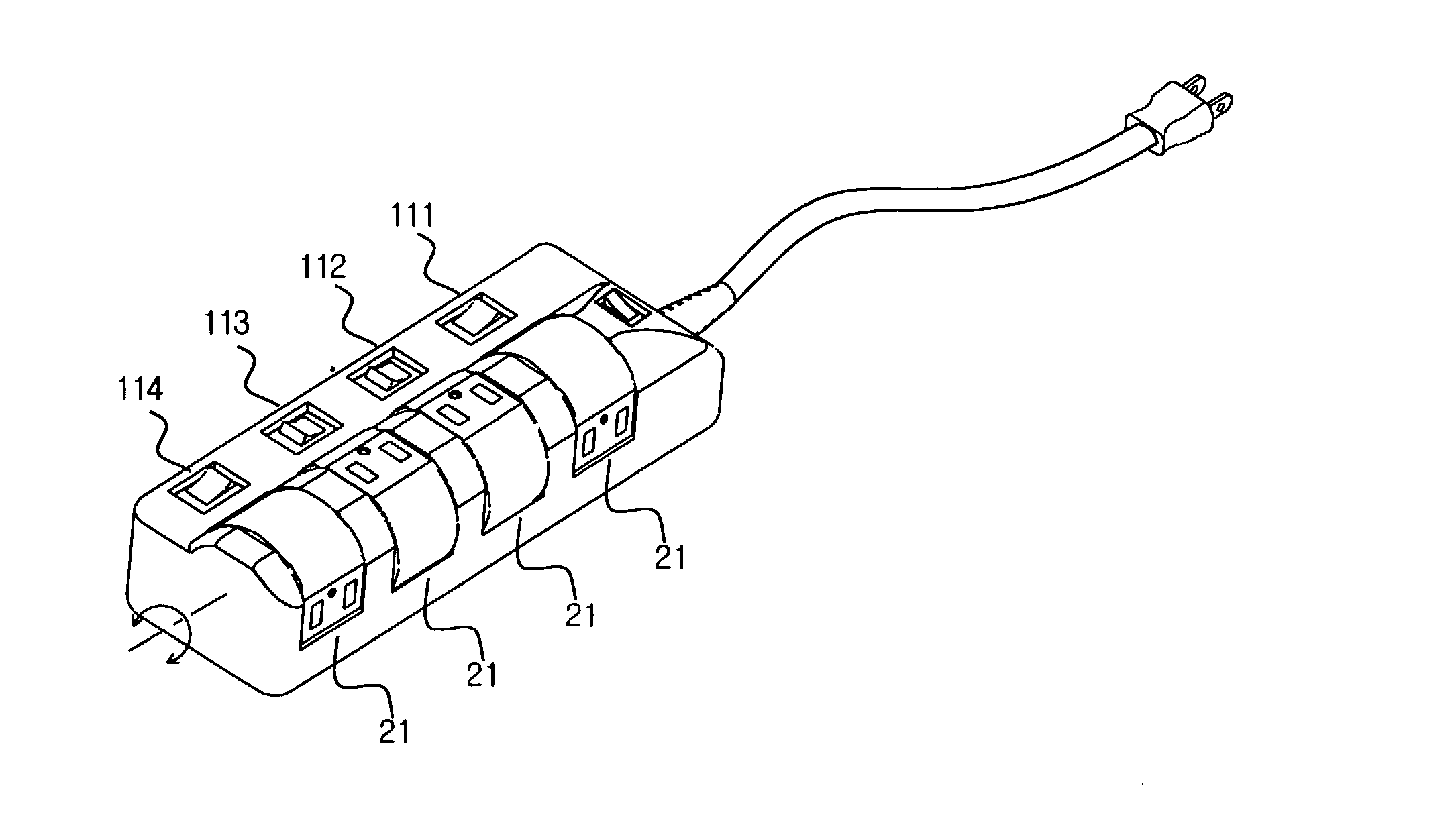
[0085] FIG. 6 illustrates the present invention. In this embodiment of the present invention, the power control apparatus includes a plurality of switches 300 for connecting or disconnecting the power to receptacle 320. Switches 300 are separated from each other by a barrier formed between the neighboring switches.
[0086] As shown in FIG. 6, a number of switches 300 are installed along the side of one edge at a lower surface than the top surface of housing H where receptacles 320 are located. Each switch 300 is separately installed in a compartment of housing H with a common lid 330. It is possible that this feature will prevent accidental operation of the switch by the turning on or off of a wrong switch. Because barrier wall 310, consisting of a compartment and lid, covers each switch 300 individually, it is possible to prevent erroneous operation of switch 300. For example, a user may step on or press down the switch unintentionally by his body or drop an object on the switch acci...
fourth embodiment
[0089] the present invention is shown in FIG. 9. As shown, the power control apparatus includes a plurality of switches 610 for connecting or disconnecting the electric power to a plurality of receptacles 620. The switches 610 are installed at a concaved area 600 lower than the top surface of housing H. There is a slanted surface between the concaved area 600 and the top surface of the housing. Concave area 600 is formed for installing switches 610, and switches 610 are installed to correspond with receptacle 620. Further, the depth of concave area 600 is the same as the height of switches 610 or slightly deeper than the heights of switches 610.
[0090] FIG. 10 is a cross section view taken along the line A-A of FIG. 9. As shown, switch 610 is installed at concave area 600 formed on the top surface of housing H. The abutted area between concave area 600 and the top surface of housing H has slanted 601 at the opposite end. The slanted part 601 is for the comfort of the operator's finge...
PUM
| Property | Measurement | Unit |
|---|---|---|
| Length | aaaaa | aaaaa |
| Time | aaaaa | aaaaa |
| Diameter | aaaaa | aaaaa |
Abstract
Description
Claims
Application Information
 - R&D
- Intellectual Property
- Life Sciences
- Materials
- Tech Scout
- Unparalleled Data Quality
- Higher Quality Content
- 60% Fewer Hallucinations
Browse by: Latest US Patents, China's latest patents, Technical Efficacy Thesaurus, Application Domain, Technology Topic, Popular Technical Reports.
© 2025 PatSnap. All rights reserved.Legal|Privacy policy|Modern Slavery Act Transparency Statement|Sitemap|About US| Contact US: help@patsnap.com


