Fiber optic coupler with in-line optical component

a technology optical components, applied in the field of fiber optic couplers, can solve the problems of large size, high cost, and relatively high cost of lenses

Inactive Publication Date: 2003-01-09
THE JOHN HOPKINS UNIV SCHOOL OF MEDICINE
View PDF0 Cites 32 Cited by
  • Summary
  • Abstract
  • Description
  • Claims
  • Application Information

AI Technical Summary

Problems solved by technology

These lenses are relatively expensive, typically costing hundreds of dollars and being the most expensive components in the bench top device.
Such bench top devices are sufficiently large in size, e.g., approximately three inches by six inches by two inches, to be unsuitable for use in typical hand-held devices.
Such an arrangement is wasteful of optical component materials and contributes unnecessarily to the cost of the device.
Additionally, bench top devices require a high degree of precision in alignment of the fibers and optical component, and are therefore subject to a r...

Method used


Image

  • Fiber optic coupler with in-line optical component
  • Fiber optic coupler with in-line optical component
  • Fiber optic coupler with in-line optical component

Examples


Embodiment Construction

)

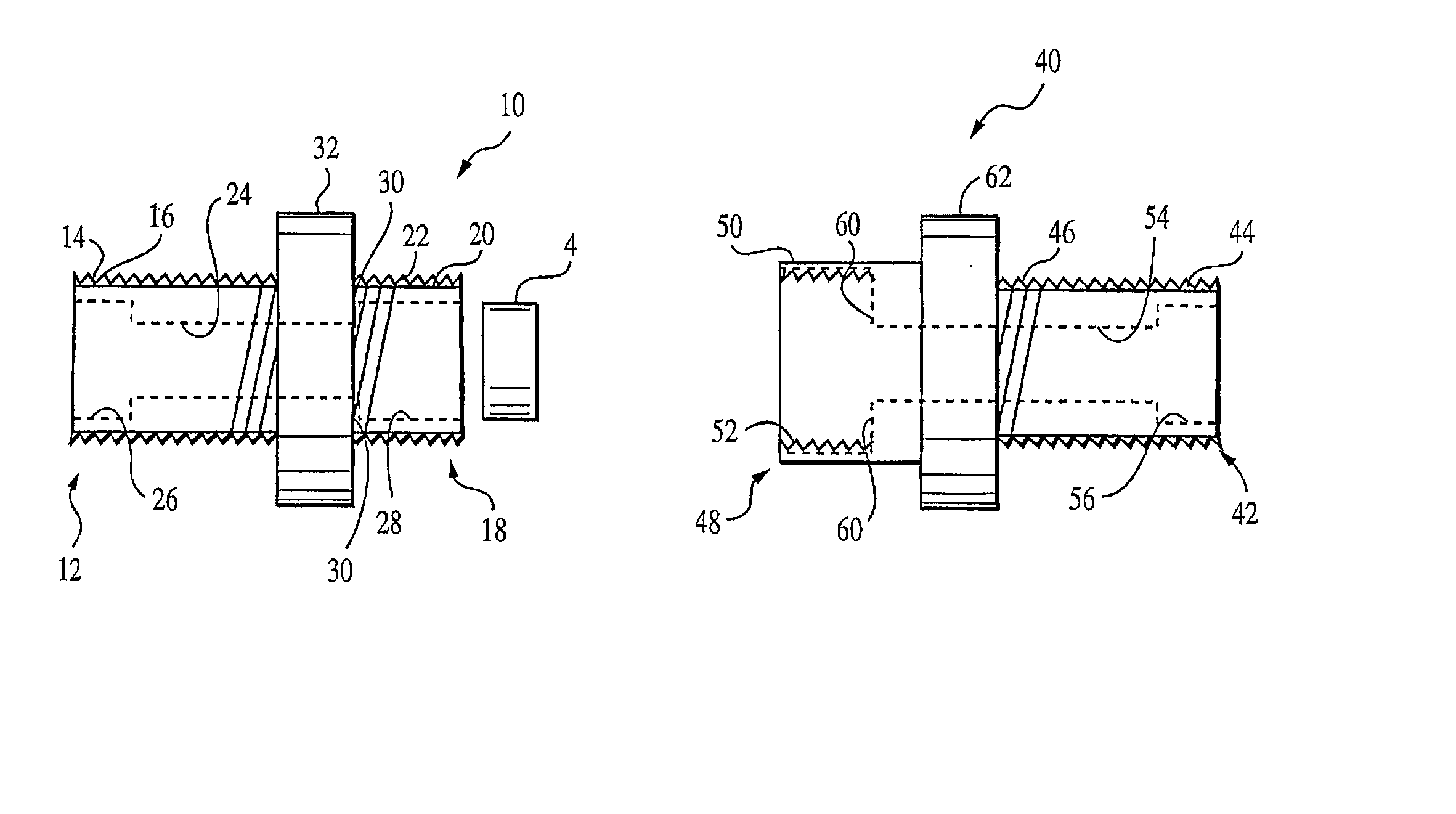
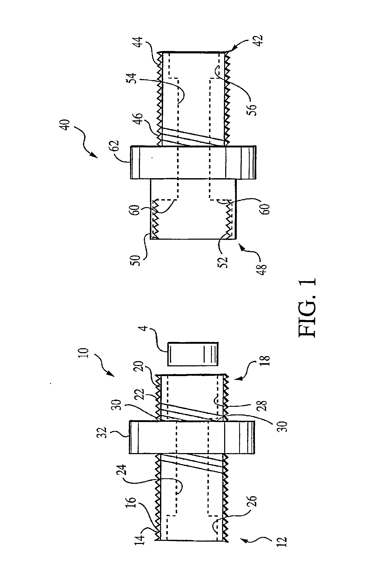
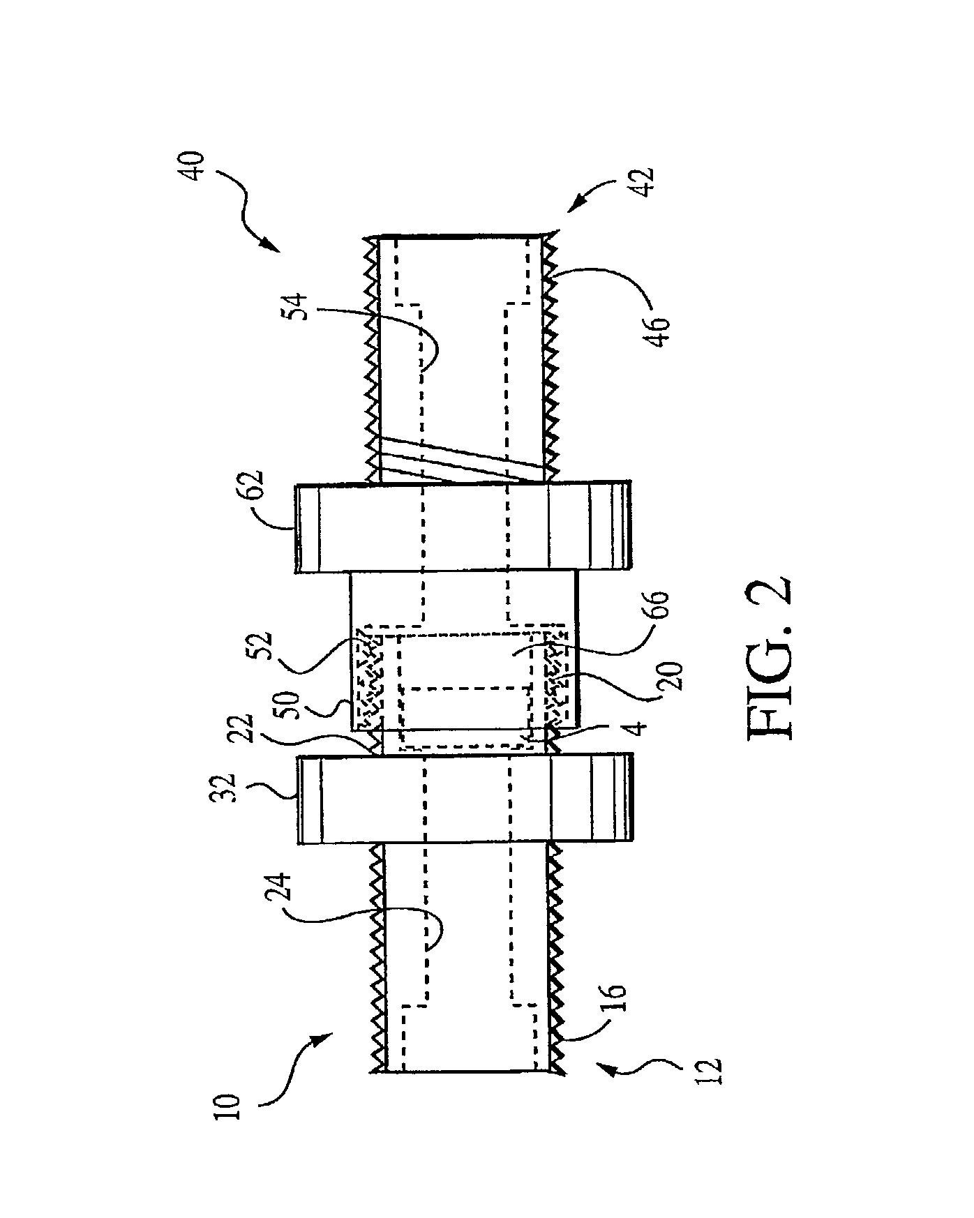
[0023] The present invention provides a fiber optic coupler with in-line optical component. The coupler may be used for coupling a first fiber optic cable terminating in a first connector to a second fiber optic cable terminating in a second connector. A fiber optic coupler in accordance with the present invention may be configured for use with fiber optic cable terminating in various types of connectors including, for example, SMA, FC, ST, LC, and SC, type connectors. These and other connectors are well known in the art and therefore there is no need to illustrate each of them herein. FIGS. 1-4 show an exemplary fiber optic coupler according to a first embodiment of the present invention for coupling SMA-type connectors.

[0024] Conceptually, the fiber optic coupler of the present invention is a compact, lens-free design that holds an optical element and allows for aligning and coupling of two fiber optic connectors with the optical component therebetween, leaving the optical fibers...


PUM


Abstract

A coupler for coupling first and second fiber optic cables terminating in first and second connectors having first and second ferrules, respectively. The coupler includes a holder element and a mating element. The holder element defines a channel for receiving the first ferrule and a socket aligned with the channel for receiving an optical component The holder element further defines a first cable connector adapted for connection to the first connector and a first element connector opposite said first cable connector. The mating element defines a channel for receiving the second ferrule, a second cable connector adapted for connection to the second connector and a second element connector opposite the second cable connector. Accordingly, the holder element and mating element are connectable to house an optical component aligned with the channels and positionable substantially contiguous with the first and second ferrules when attached thereto.

Description

[0001] This application claims the benefit of prior filed co-pending U.S. Provisional application No. 60 / 219,398, filed on Jul. 19, 2000, the disclosure of which is hereby incorporated herein by reference.[0002] 1. Field of the Invention[0003] The present invention relates generally to fiber optic couplers and particularly to a fiber optic coupler with an in-line optical component.[0004] 2. Description of the Related Art[0005] In the field of fiber optics, it is often necessary to operate on an optical beam carried by an optical fiber using an optical component. For example, such optical components may include filters, such as colored glass, interference or neutral density filters, e.g. for blocking out or passing specific wavelengths of light, attenuators for reducing optical power to a desired range, polarizers for controlling the polarization of light, and isolators for preventing back reflections and other noise from reaching sensitive optical components. Such optical components...

Claims


Application Information

Patent Timeline
IPC IPC(8): G02B6/26G02B6/38
CPCG02B6/264G02B6/266G02B6/3825G02B6/3891G02B6/3894
Inventor PERRY, ALEXANDER S.MURRAY, GEORGE M.
Owner THE JOHN HOPKINS UNIV SCHOOL OF MEDICINE
Why Eureka
Try Eureka