Imaging lens, image reader using the lens, and imaging apparatus using the image reader

Inactive Publication Date: 2003-01-16
RICOH KK
View PDF1 Cites 21 Cited by
  • Summary
  • Abstract
  • Description
  • Claims
  • Application Information

AI Technical Summary

Benefits of technology

0019] It is another object of the invention to provi

Problems solved by technology

The above-described problems in the conventional imaging lens and the image reader are serious because the reproduced image quality deteriorates, and therefore, a technique for outputting more uniform signals from the CCD array at each image height is desired.
However, the resolution in the sub scanning direction indicated by the solid line does not reach the threshold level, and consequently, the resolution of the reproduced image deteriorates in the sub scanning direction.
If it is found after the focus adjustment that the resolution in the sub scanning direction is insufficient, the positional relation between the imaging lens 1004 and the CCD 1005 has to be adjusted again, and the adjusting process becomes troublesome as a whole.
If the performance of the actually used imaging lens differs from the reference due to variation in the components of the imaging lens within the tolerance, then the focal point can not be correctly brought into the desig

Method used


Image

  • Imaging lens, image reader using the lens, and imaging apparatus using the image reader
  • Imaging lens, image reader using the lens, and imaging apparatus using the image reader
  • Imaging lens, image reader using the lens, and imaging apparatus using the image reader

Examples


first embodiment

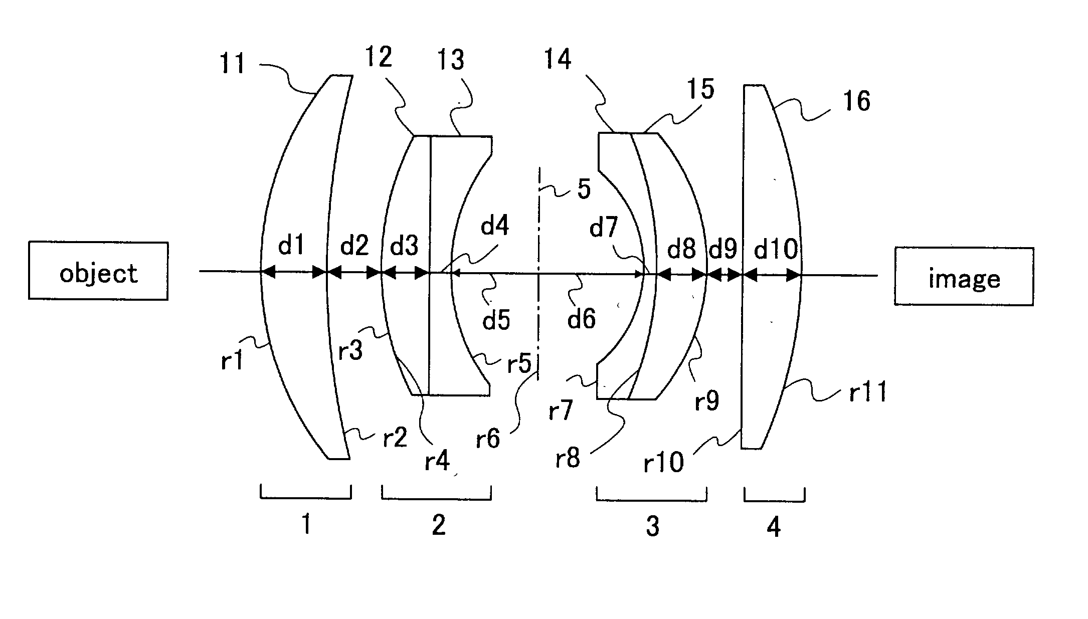
[0066] FIG. 5 illustrates the structure of an imaging lens 10 according to the The imaging lens 10 comprises the first through forth (1-4) lens groups from the object, and a stop (diaphragm) 5 placed between the second and the third lens groups.

[0067] The first lens group 1 includes a first lens 11, which is a meniscus lens having a convex surface on the object side. The second lens group 2 includes a second lens 12 with a positive index of refraction, and a third lens 13 bonded to the second lens 12. The third lens group 3 includes a fourth lens 14 with a negative index of refraction, and a fifth lens 15 bonded to the fourth lens 14 and having a positive index of refraction. The fourth lens group 4 includes a sixth lens 16 with a positive index of refraction. This imaging lens has a 4-group 6-lens structure.

[0068] The characteristics and the parameters of the lenses 11-16 are listed in Table 1.

1TABLE 1 f = 50 F / No. = 4.0 .omega. = 16.9 Y = 152.4 r1 22.161 d1 4.86 n1 1.79152 .nu.1 ...

second embodiment

[0087] FIG. 11 illustrates an image reader 70 according to the The image reader 70 comprises a light source (not shown) for illuminating an image formed on an original (not shown), a CCD 76, first through third mirrors 71-73 for guiding a light image reflected from the original to the CCD 76, an imaging lens 74 for converging the light image guided by the mirrors 71-73 onto the CCD 76, and a member 75 having an anamorphic surface inserted in the light path from the-original to the CCD 76. In the example shown in FIG. 11, the member 75 having at least one anamorphic surface is inserted between the imaging lens 74 and the CCD 76.

[0088] The original is placed on a stage (not shown, see FIG. 1), and the image information on the original is scanned, while the image is illuminated by the light source (not shown). The light beam reflected from the original is reflected by the first through third mirrors 71-73, as illustrated in FIG. 11. The first mirror 71 and the light source (not shown)...

third embodiment

[0116] In the third embodiment, the image reader 90 not only achieves the consistent imaging positions in the main and sub scanning direction at each image height, but also brings the imaging positions of R, G and B into consistency with the target plane. To achieve this, the first through third mirrors 94-96 are furnished with anamorphic surfaces 94b-96b, respectively, so that the R, G, and B signals output from the CCD 98 become uniform at each image height.

[0117] In the example shown in FIG. 13, the first mirror 94 has a first surface 94a, which is the incident surface the light beam strikes, and a second surface 94b, which is opposite to the first surface and is the anamorphic surface. Similarly, the second mirror 95 has a first surface (i.e., the incident surface) 95a and a second surface (i.e, the anamorphic surface) 95b. The third mirror 96 has a first surface (i.e., the incident surface) 96a, and a second surface (i.e, the anamorphic surface) 96b.

[0118] The first surface 94a...


PUM


Abstract

An imaging lens comprises a first, a second, a third, and a fourth lens group from an object toward an image. The first lens group includes a first lens that is a convex meniscus lens with a convex surface on the object side. The second lens group includes a second lens having a positive refractive power, and a third lens bonded to the second lens and having a negative refractive power. The third lens group includes a fourth lens having a negative refractive power, and a fifth lens bonded to the fourth lens and having a positive refractive power. The fourth lens group includes a sixth lens having a positive refractive power. The imaging lens satisfies the condition <paragraph lvl="0"><in-line-formula>0.10<D/f<0.19 </in-line-formula>where D denotes a sum of an air gap between the first lens and the second lens and an air gap between the fifth lens and the sixth lens, and f denotes a focal length of the entirety-of the imaging lens with respect to an e-ray.

Description

[0001] 1. Field of the Invention[0002] The present invention generally relates to a technique for reading an image formed on a medium using solid-state image pickup devices, such as line sensors (e.g., CCDs), as well as to its applications, and more particularly, to an imaging lens, an image reader, and an imaging apparatus using the image reader.[0003] 2. Description of the Related Art[0004] In general, image readers applied to imaging apparatuses, such as digital photocopiers, image scanners, or facsimile machines, optically read the image information on an original, and convert the optical image to electric signals. The optical image reflected from the original is reduced and focused on a solid-state image pickup device, such as a CCD array or a line sensor, using the imaging lens furnished in the image reader.[0005] FIG. 1 schematically illustrates an example of the conventional image reader assembled in a digital photocopier. The original 1006 placed on the stage 1001 is scanne...

Claims


Application Information

Patent Timeline
IPC IPC(8): G02B13/00G02B13/18G02B13/24G03B27/50H04N1/028
CPCG02B13/24
Inventor MIYATAKE, NAOKI
Owner RICOH KK
Why Eureka
Try Eureka