Ballast for operating at least one low-pressure discharge lamp

a low-pressure discharge and ballast technology, applied in the direction of light sources, electric lighting sources, lighting devices, etc., to achieve the effect of improving the luminous efficiency and controlling the brightness of the lamp

Inactive Publication Date: 2003-01-23
PATENT TREUHAND GESELLSCHAFT FUR ELECTRIC GLUEHLAMPEN MBH
View PDF0 Cites 23 Cited by
  • Summary
  • Abstract
  • Description
  • Claims
  • Application Information

AI Technical Summary

Benefits of technology

[0024] Both transformers act as differential current transformers. The first transformer ensures balancing of the currents in the two parallel-connected branch circuits, while the second transformer causes balancing of the total current upstream and downstream of the parallel connection of the branch circuits. The first transformer ensures that the lamps in the two branch circuits shine with the same brightness, while the second transformer ensures that the lamps arranged in the same branch circuit--that is to say the series-connected lamps of each branch circuit shine with the same brightness. The second transformer compensates the losses that are produced by parasitic capacitances. In its attempt to cause equal currents to flow in its windings, it balances the leakage currents caused by parasitic capacitances. In this process, it lowers the potential of the lamp terminal assigned to the capacitor C1, while it correspondingly raises the potential of the lamp terminal assigned to the capacitor C2. This ballast is therefore particularly well suited for operating four low-pressure discharge lamps that are arranged in two parallel branch circuits with in each case a series connection composed of two low-pressure discharge lamps. This variant of the ballast is, however, also suitable for operating a different number of low-pressure discharge lamps in the two parallel-connected branch circuits. For example, it is possible to arrange two series-connected low-pressure discharge lamps in the first branch circuit, and to operate only one low-pressure discharge lamp in the second branch circuit.
[0027] The ballast according to the invention is advantageously designed as an inverter with a downstream load circuit, the electric terminals for the low-pressure discharge lamps or the branch circuits with the electric terminals for at least one low-pressure discharge lamp being arranged in the load circuit, in order to be able to operate the lamps with the aid of a high-frequency alternating current. The operation of the lamps with the aid of a high-frequency alternating current improves the luminous efficiency and enables the brightness of the lamps to be controlled in a simple way by changing the frequency of the alternating current.

Problems solved by technology

The problem frequently arises in the case of ballasts for operating a plurality of low-pressure discharge lamps that the lamps shine with a different brightness in the dimming mode.
If the lamps are arranged in different, parallel-connected branch circuits, this problem can be caused by different currents in the branch circuits.
On the other hand, however, this problem also occurs with lamps that--as in the case of a series connection of two lamps--are arranged in the same branch circuit.
The aforesaid problems are caused by parasitic capacitances between the lamp or the lamp leads and the luminaire and also by parasitic capacitances inside the heating circuit.

Method used


Image

  • Ballast for operating at least one low-pressure discharge lamp
  • Ballast for operating at least one low-pressure discharge lamp
  • Ballast for operating at least one low-pressure discharge lamp

Examples


Embodiment Construction

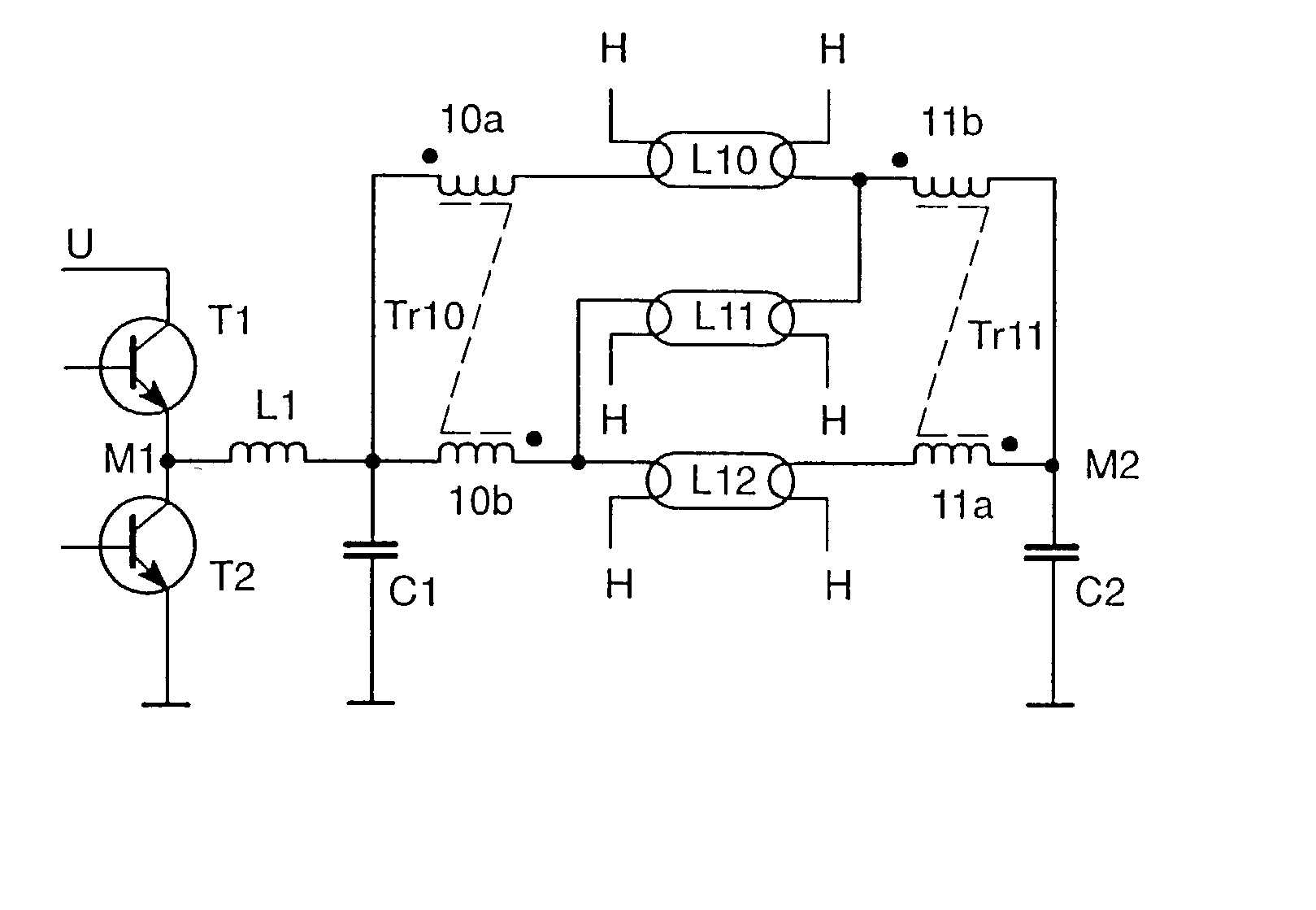
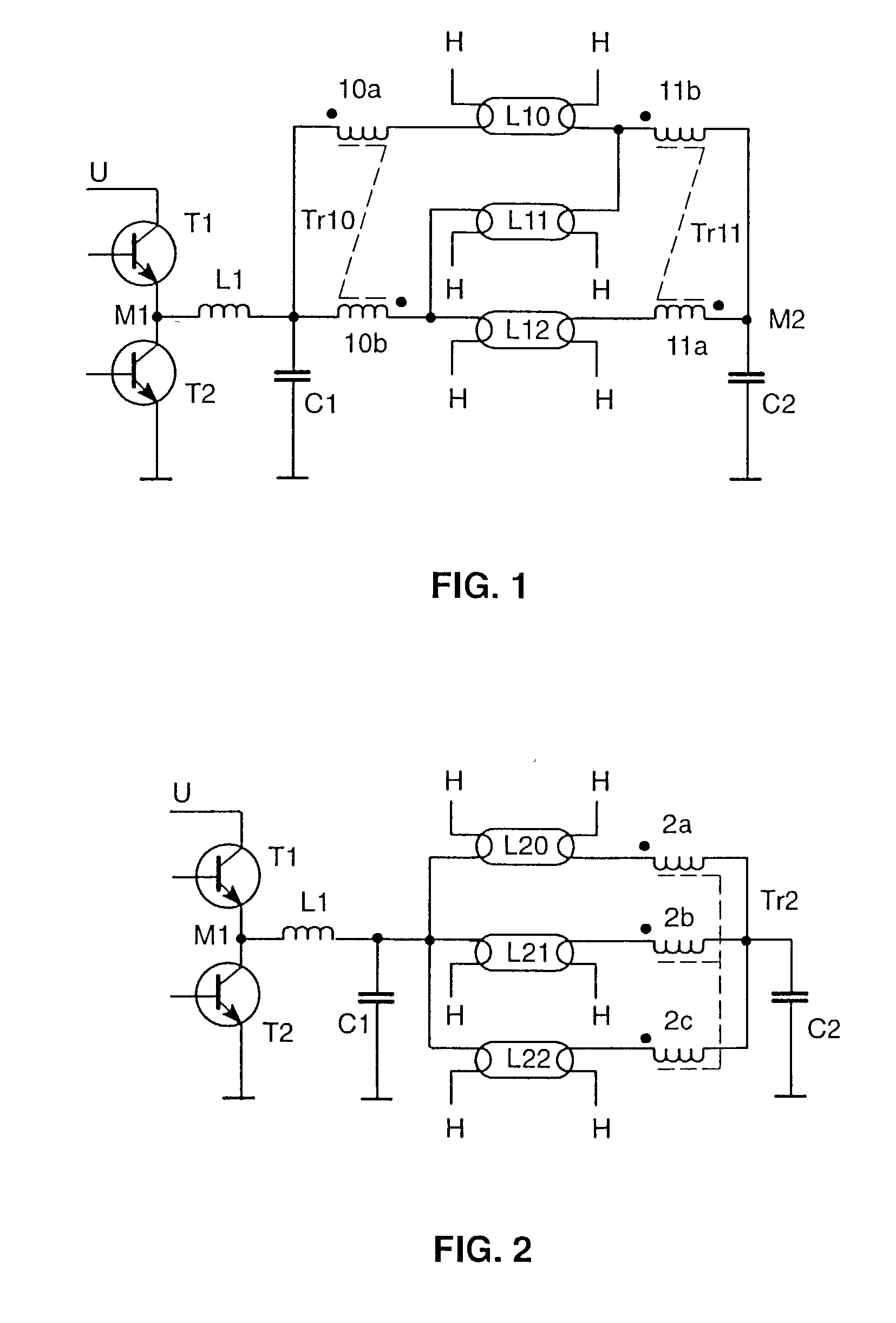
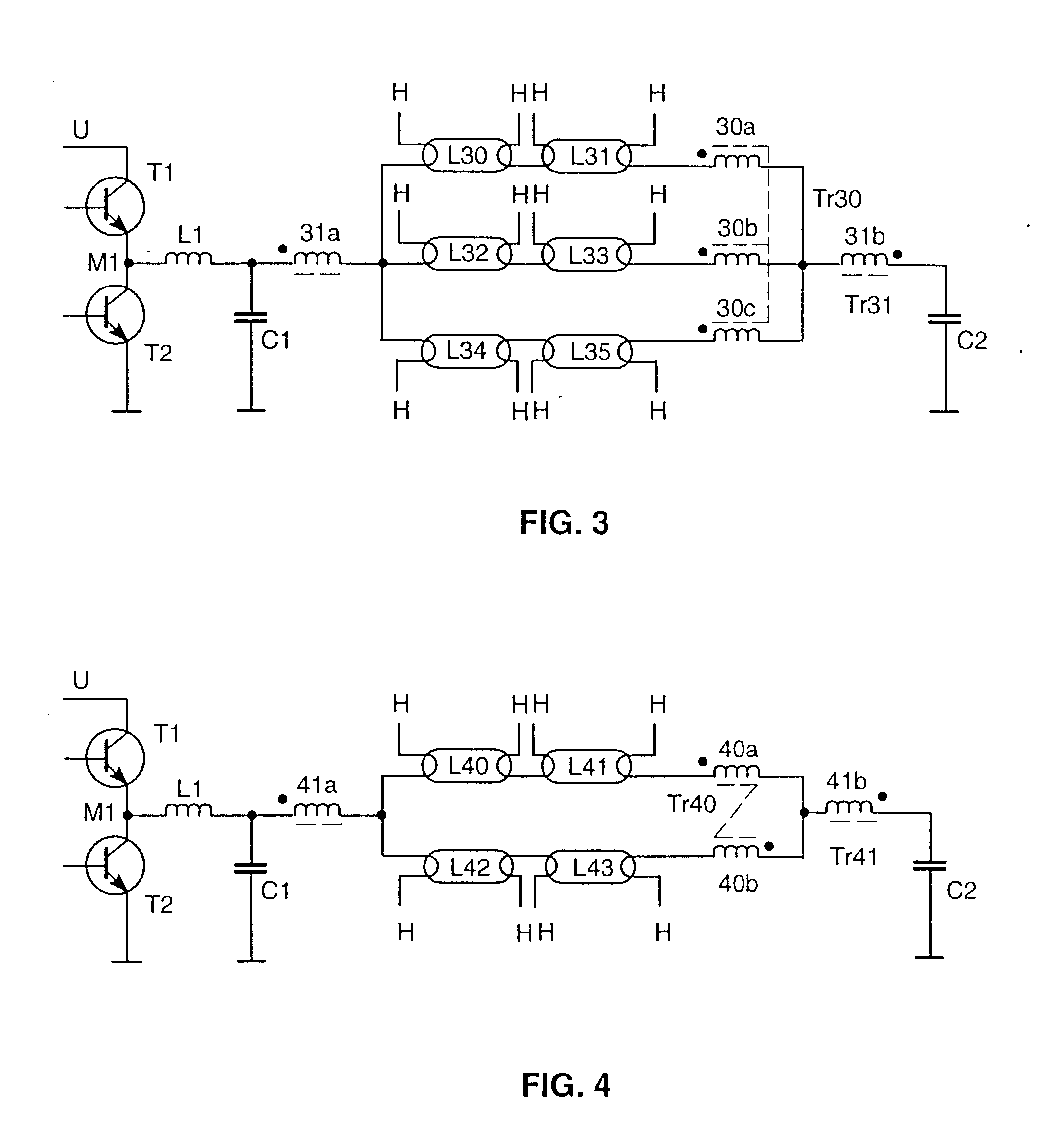
[0038] In FIGS. 1 to 8, the same reference symbols have been selected for identical components of the ballast or of the circuit arrangement. In the case of all exemplary embodiments of the invention, the ballast has a half-bridge inverter that essentially comprises the transistors T1, T2 and a drive device (not illustrated) for the transistors T1, T2, as well as the half-bridge capacitor C2. The half-bridge inverter T1, T2 is supplied at its voltage inputs with a DC voltage U that is generated in a known way by filtering and rectifying the AC supply voltage. The filter and rectifier circuits of the ballast are therefore not illustrated in the figures and are also not intended to be further described here. The inductor L1 is connected to the center tap M1 between the transistors T1, T2 of the half-bridge inverter. Connected to the inductor L1 is the first terminal of the capacitor C1, while the second terminal of the capacitor C1 is connected to frame potential. The inductor L1 and t...


PUM


Abstract

The invention relates to a ballast for operating at least one low-pressure discharge lamp, preferably a three- or four-lamp ballast. In order for all parallel- or series-connected low-pressure discharge lamps (L40-L43) to shine equally bright even in the case of strong dimming, the ballast according to the invention has a transformer (Tr40) for balancing the currents in the lamp branch circuits and a transformer (Tr41) for compensating the losses owing to parasitic capacitances.

Description

I. TECHNICAL FIELD[0001] The invention relates to a ballast for operating at least one low-pressure discharge lamp.II. BACKGROUND ART[0002] U.S. Pat. No. 4,392,085 discloses a ballast for operating two parallel-connected low-pressure discharge lamps on a half-bridge inverter. The ballast has a transformer with two similar windings that are each connected to one of the two lamp branch circuits. This transformer operates as a differential current transformer. If one of the two lamps ignites earlier than the other, the ignition of the other lamp is supported with the aid of the transformer.III. DISCLOSURE OF THE INVENTION[0003] The problem frequently arises in the case of ballasts for operating a plurality of low-pressure discharge lamps that the lamps shine with a different brightness in the dimming mode. If the lamps are arranged in different, parallel-connected branch circuits, this problem can be caused by different currents in the branch circuits. On the other hand, however, this ...

Claims


Application Information

Patent Timeline
Patent Type & Authority Applications(United States)
IPC IPC(8): H05B41/282
CPCH05B41/2827
Inventor KLIER, JUERGENTWARDZIK, RENE
Owner PATENT TREUHAND GESELLSCHAFT FUR ELECTRIC GLUEHLAMPEN MBH
Why Eureka
Try Eureka