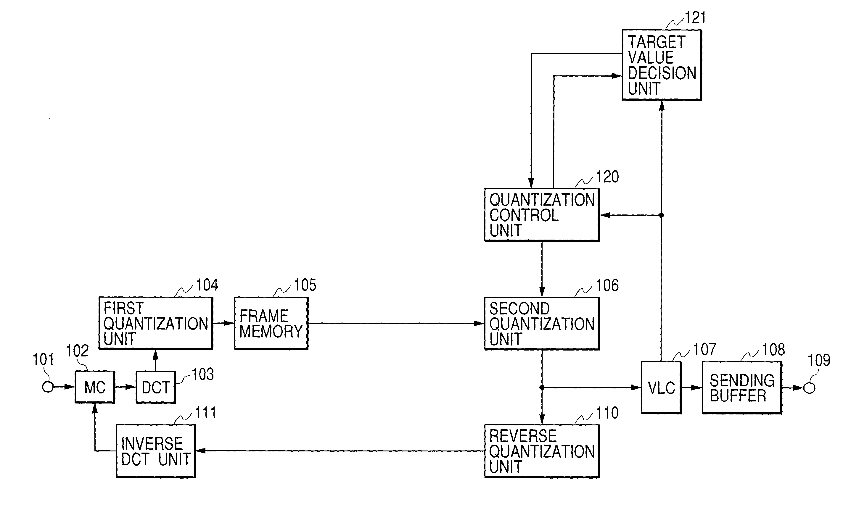
Dynamic image compression coding apparatus
a compression coding and dynamic image technology, applied in the field of dynamic image coding method, can solve the problems of increasing quantization distortion, deteriorating picture quality, and enormous throughpu
- Summary
- Abstract
- Description
- Claims
- Application Information
AI Technical Summary
Problems solved by technology
Method used
Image
Examples
first embodiment
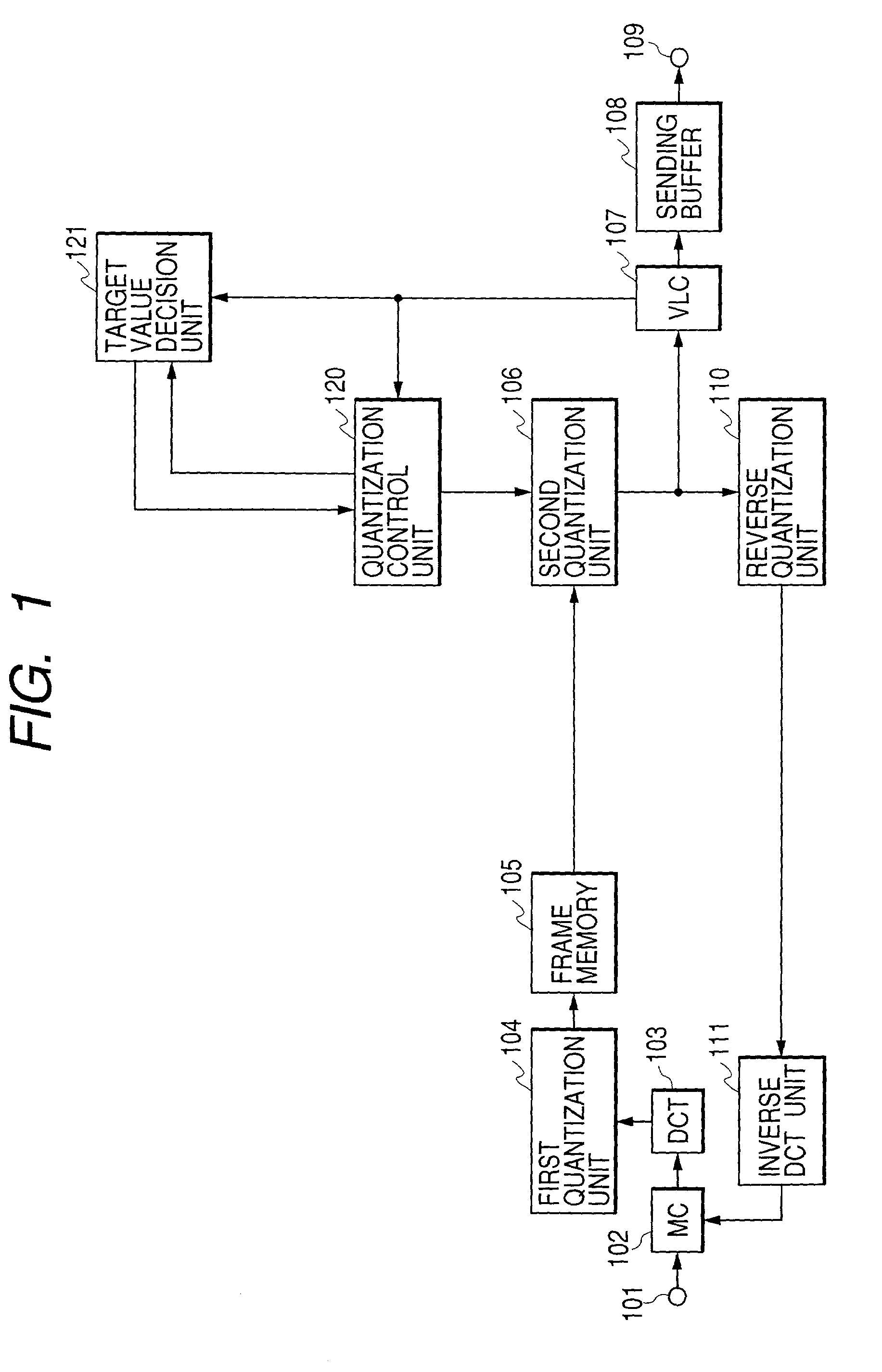
[0028] FIG. 1 shows a block diagram of the dynamic image compression coding apparatus of the The dynamic image compression coding apparatus of FIG. 1 is provided with a digital dynamic image input terminal 101, an MC unit 102 that is a motion compensation means, a DCT unit 103 that is a DCT conversion means, a first quantization unit 104 that is a first quantization means, a frame memory 105 that is a storage means, a second quantization unit 106 that is a second quantization means, a VLC unit 107 that is a coding means, a sending buffer 108, a bit stream output terminal 109, a reverse quantization unit 110, an inverse DCT unit 111, a quantization control unit 120 that is a quantization control means, and a target value decision unit 121 that is a target code amount decision means. The MC is an abbreviation of motion compensation, and the VLC is an abbreviation of variable length coding. A combination of the quantization control unit 120 and the target value decision unit 121 may a...
second embodiment
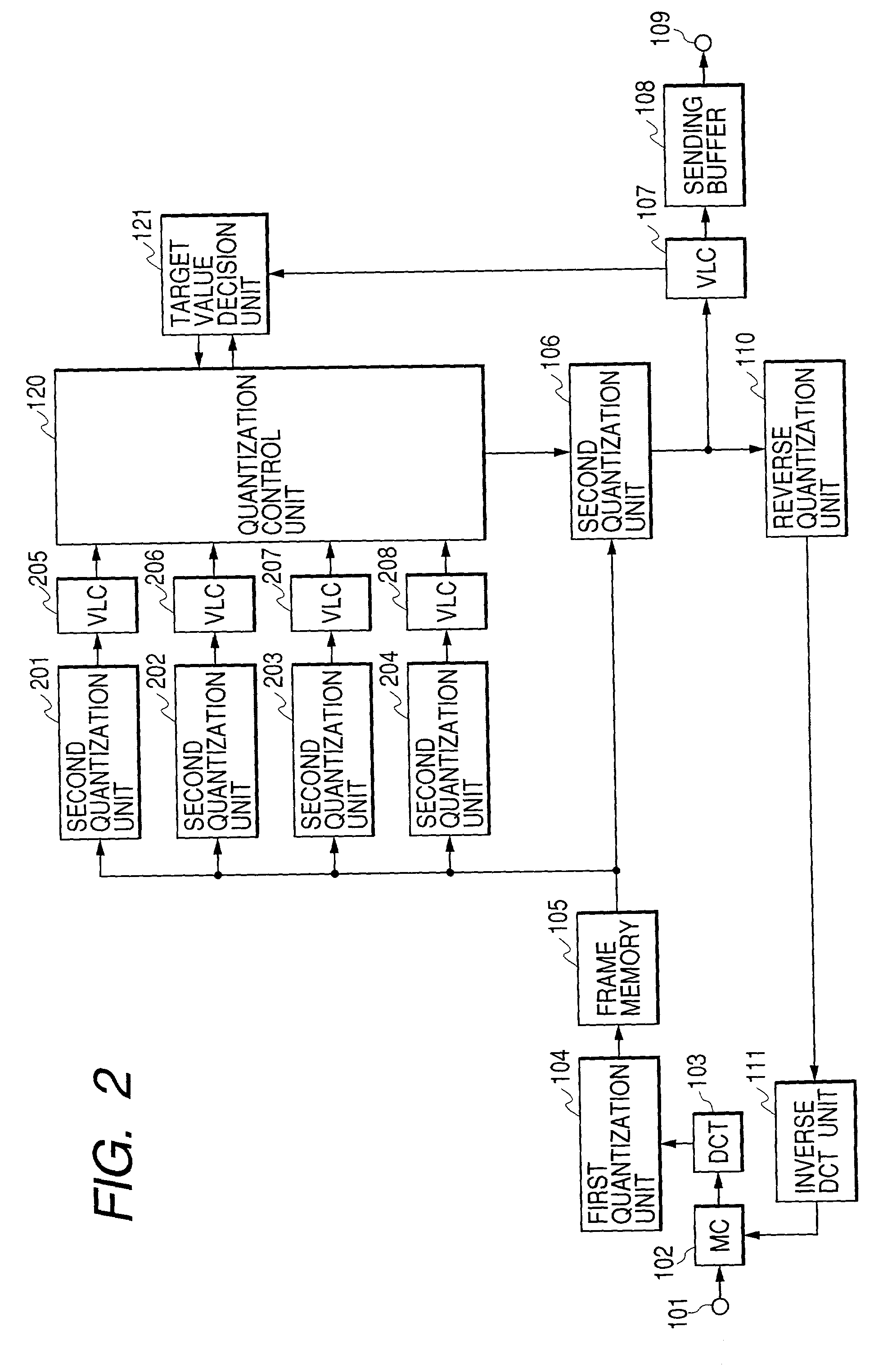
[0044] The second embodiment uses the same quantization scale in each macro block in a picture. By using the same quantization scale, the degree of quantization distortion is made uniform and the picture quality in a picture is made uniform. On the other hand, from the viewpoint of code amount control, the code amount generated in the picture need match the target code amount of the picture. When the same quantization scale is used in each macro block in the picture, the quantization scale that generates the code amount most approximate to the target code amount of the picture must be decided. To solve this problem, a generated code amount estimation system is provided, a generated code amount for the quantization scale is estimated, and the quantization scale that generates the code amount most approximate to the target code amount is selected.
[0045] FIG. 2 shows a block diagram of the second embodiment. The dynamic image compression coding apparatus is provided with the digital dy...
fifth embodiment
[0072] The fifth embodiment uses the same quantization scale in each block in a picture. By using the same quantization scale, the degree of quantization distortion is made uniform and the picture quality of the picture is made uniform. On the other hand, from the viewpoint of code amount control, the code amount generated in the picture need match the target code amount of the picture. When the same quantization scale is used in each macro block in the picture, the quantization scale that generates the code amount most approximate to the target code amount of the picture must be decided.
[0073] The fifth embodiment decides a quantization scale using what is called a "pincer attack" method. In MPEG-2, when the same data is encoded, a code amount is reduced as the quantization scale increases. When the code amount obtained by performing coding using a quantization scale Qa is smaller than the target code amount and the code amount obtained by performing coding using a quantization sca...
PUM
 Abstract
Description
Claims
Application Information
 - R&D
- Intellectual Property
- Life Sciences
- Materials
- Tech Scout
- Unparalleled Data Quality
- Higher Quality Content
- 60% Fewer Hallucinations
Browse by: Latest US Patents, China's latest patents, Technical Efficacy Thesaurus, Application Domain, Technology Topic, Popular Technical Reports.
© 2025 PatSnap. All rights reserved.Legal|Privacy policy|Modern Slavery Act Transparency Statement|Sitemap|About US| Contact US: help@patsnap.com


