Metalized shrink label and related method of manufacture

a shrink label and metalized technology, applied in the field of shrink labels and, can solve the problems of affecting the overall affecting the appearance of the article, and limiting the use of the object, so as to enhance the overall appearance or image or graphics

Inactive Publication Date: 2003-01-30
UV COLOR +1
View PDF0 Cites 44 Cited by
  • Summary
  • Abstract
  • Description
  • Claims
  • Application Information

AI Technical Summary

Benefits of technology

[0005] The aforementioned problems are overcome in the present invention wherein a shrink film includes a metallic or reflective layer. More particularly, the metalized shrink film of the present invention includes a shrink film, a layer of varnish or plastic extrusion disposed over a surface of the shrink film, and a metallic or reflective layer--the "metalized layer"--disposed over the varnish or plastic extrusion layer. This metalized shrink film may be incorporated into shrink sleeves or labels. Preferably, the varnish is clear, and portions of the metalized layer are viewable through the shrink film to enhance images or graphics or the overall appearance of the article to which the heat shrink label is applied.
[0006] With the construction of the present invention, it is possible to enhance images and graphics on shrink labels with highly reflective or metallic-like effects because the layer of varnish or plastic extrusion prevents or at least minimizes metalized layers from discoloring and becoming cloudy or hazy when the label is shrunk over contours of articles.

Problems solved by technology

Many attempts have been made to enhance the graphics, images, or overall aesthetic appeal of shrink labels, however, these attempts usually are limited by distortion of the shrink label around contours of articles during shrinkage.
Although this application enhances the appearance of a shrink label in its un-shrunken state, after the label is shrunken onto an article, the silver ink becomes hazy, cloudy and generally discolored near the contours.

Method used


Image

  • Metalized shrink label and related method of manufacture
  • Metalized shrink label and related method of manufacture

Examples


Embodiment Construction

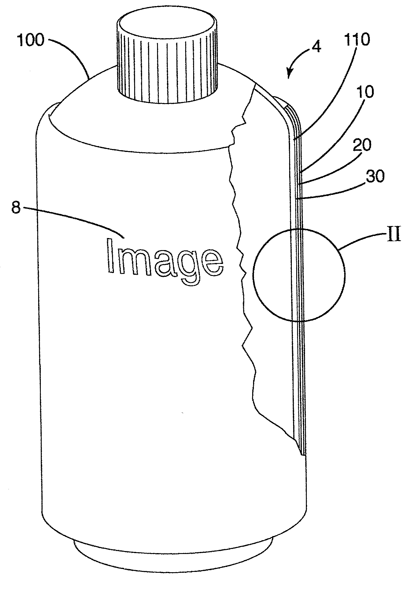
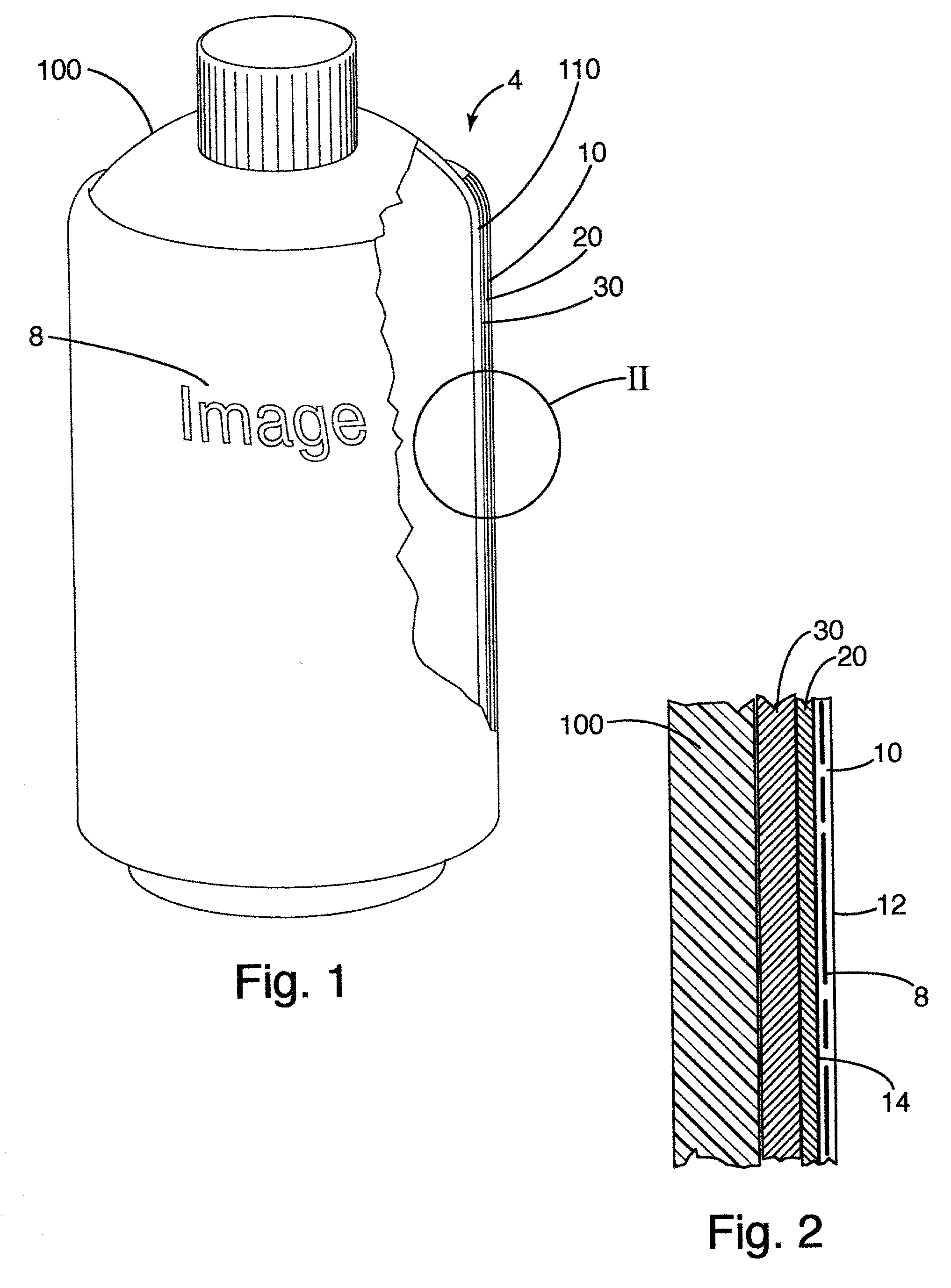
[0011] The preferred metalized shrink film of the present invention will be described in connection with a metalized shrink label 4 applied to bottle 100 as shown in FIGS. 1 and 2. The metalized shrink label generally includes shrinkable film layer 10, varnish layer 20 and metalized layer 30.

[0012] As shown in FIG. 1, the metalized shrink label (exaggerated in thickness) is in the form of a shrink sleeve, conforming to the contours 110 of the bottle 100. It will be appreciated that the construction of the shrink label used in any application where a shrink label or sleeve is desired. Accordingly, when used herein, shrink label refers to any shrink label construction, including a shrink sleeve.

[0013] With further reference to the blown-up view of the shrink label 4 in FIG. 2, the shrinkable film layer 10 is constructed from any material capable of shrinking when subjected to a physical condition. Preferably, the shrinkable film layer shrinks in response to the application of heat the...


PUM

PropertyMeasurementUnit
heat shrinkaaaaaaaaaa
areaaaaaaaaaaa
transparentaaaaaaaaaa

Abstract

A metalized shrink film for contoured containers and other articles and a process for manufacturing the same. A preferred metalized shrink film includes a heat-shrinkable film layer, a varnish disposed over the film on at least one side, and a metalized layer disposed over the varnish. The metalized layer is preferably viewable through the heat-shrinkable film layer. Preferably, the varnish is a clear and ultraviolet curable, and the heat-shrinkable film includes images or graphics. A preferred method of manufacturing the metalized shrink film includes: providing a heat-shrinkable film material; applying varnish over the film; and applying a metal material over the varnish and any regions of the film not covered by the varnish. Preferably, the heat shrink film is incorporated into a heat-shrinkable label or sleeve used on contoured containers, such as bottles. When the label or sleeve is shrunk over contours of the container, the metalized regions viewable through the film and the images or graphics on the film do not discolor or become cloudy near the contours.

Description

BACKGROUND[0001] The present invention relates to heat-shrink labels and sleeves for containers and other articles.[0002] A variety of labels are available to provide information or advertisements on products, typically with graphics or images printed on the viewable portion of the labels. One popular label construction is a shrink label. Shrink labels are usually applied around contoured cylindrical containers, such as bottles, cans and the like. These labels get their name from the way they are applied to the containers--a heat-shrinkable material is formed into a tube; the tube is placed over the container; the tube or container is heated; and the material shrinks around and secures the label to the container in response to the heat.[0003] Typically, a shrink label is constructed from a material that shrinks in response to heat--such as a heat-shrinkable film--so that the label readily conforms to contours of an article to which it is applied. Many attempts have been made to enha...

Claims


Application Information

Patent Timeline
Patent Type & Authority Applications(United States)
IPC IPC(8): B29C61/06B29C63/42B32B15/08B32B27/00B65D23/08
CPCB29C61/0616B29C63/42B32B15/08B32B27/00B32B38/145Y10T428/13B32B2038/0092B32B2307/412B32B2307/736B32B2519/00B65D23/0878B32B2038/0076B32B2266/0228B32B27/08B32B27/065B32B27/32B32B27/304B32B27/322
Inventor MCKILLIP, BARRON G.
Owner UV COLOR
Why Eureka
Try Eureka