Fault-tolerant routing scheme for a multi-path interconnection fabric in a storage network

a storage network and multi-path technology, applied in the field of computer systems, can solve the problems of affecting the performance of the architecture, affecting the reliability of the storage network, and affecting the reliability of the storage network, and causing the expected frequency of component failures,

Inactive Publication Date: 2003-01-30
ORACLE INT CORP
View PDF19 Cites 141 Cited by
  • Summary
  • Abstract
  • Description
  • Claims
  • Application Information

AI Technical Summary

Problems solved by technology

Such architectures may be limited in terms of performance and fault tolerance.
Also, if a storage device fails, it may be possible for that device to render the remaining devices inaccessible by corrupting the bus.
Additionally, in systems that use a single controller on each bus, a controller failure may leave all the devices on its bus inaccessible.
In a large storage array, component failures may be expected to be fairly frequent.
However, the above conventional solutions may not be adequate for such a system.
In the first solution described above, the independent buses may ease the bandwidth constraint to some degree, but the devices on each bus may still be vulnerable to a single controller failure or a bus failure.
In the second solution, a single malfunctioning device may still potentially render all of the buses connected to it, and possibly the rest of the system, inaccessible.
This same failure mechanism may also affect the third solution, since the presence of two controllers does not prevent the case where a single device failure may force the bus to some random state.
At times, adverse transmission conditions may occur in the network when one device is sending a packet to another device on the network.
For example, the network may become overly congested with packets traveling between devices.
Additionally, a fault condition, or failure in the interconnection fabric, may prevent a packet from proceeding along its proposed route.
Even these systems capable of using multiple independent paths may be susceptible to failure, though.
Generally, faults are a rare occurrence, so this configuration allows the backup paths to sit unused for long periods of time.
While the backup paths are dormant, faults may be developing in either the fail-over mechanism (e.g. fail-over software) or the backup paths themselves.
Since these backup routes are not being exercised, these errors may go undetected until the primary path fails.
Thus, a backup path may be unavailable at the very time it is critically needed.
Another concern in primary / backup systems is that the primary path may be declared permanently unavailable despite only experiencing a temporary failure.
For example, routing circuitry may experience transient or resettable faults resulting from EM-interference, alpha particle bombardment or semiconductor latch-ups.
Alternately, a message may fail to reach a destination node because a route was congested.
It may be undesirable to declare the path permanently failed in these situations since it may be usable again after the cause of the failure disappears.

Method used


Image

  • Fault-tolerant routing scheme for a multi-path interconnection fabric in a storage network
  • Fault-tolerant routing scheme for a multi-path interconnection fabric in a storage network
  • Fault-tolerant routing scheme for a multi-path interconnection fabric in a storage network

Examples


Embodiment Construction

[0039] The following figures illustrate various interconnection fabrics and nodes within interconnection fabrics that may use a routing scheme according to various embodiments of the invention. While various embodiments are explained by reference to specific interconnection fabrics, it should be readily apparent to one skilled in the art that embodiments of the present invention could be implemented in any multi-path interconnection fabric or topology.

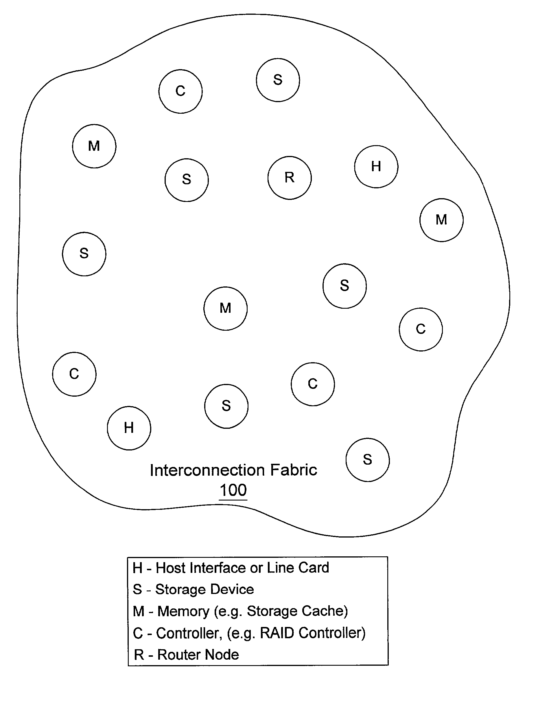
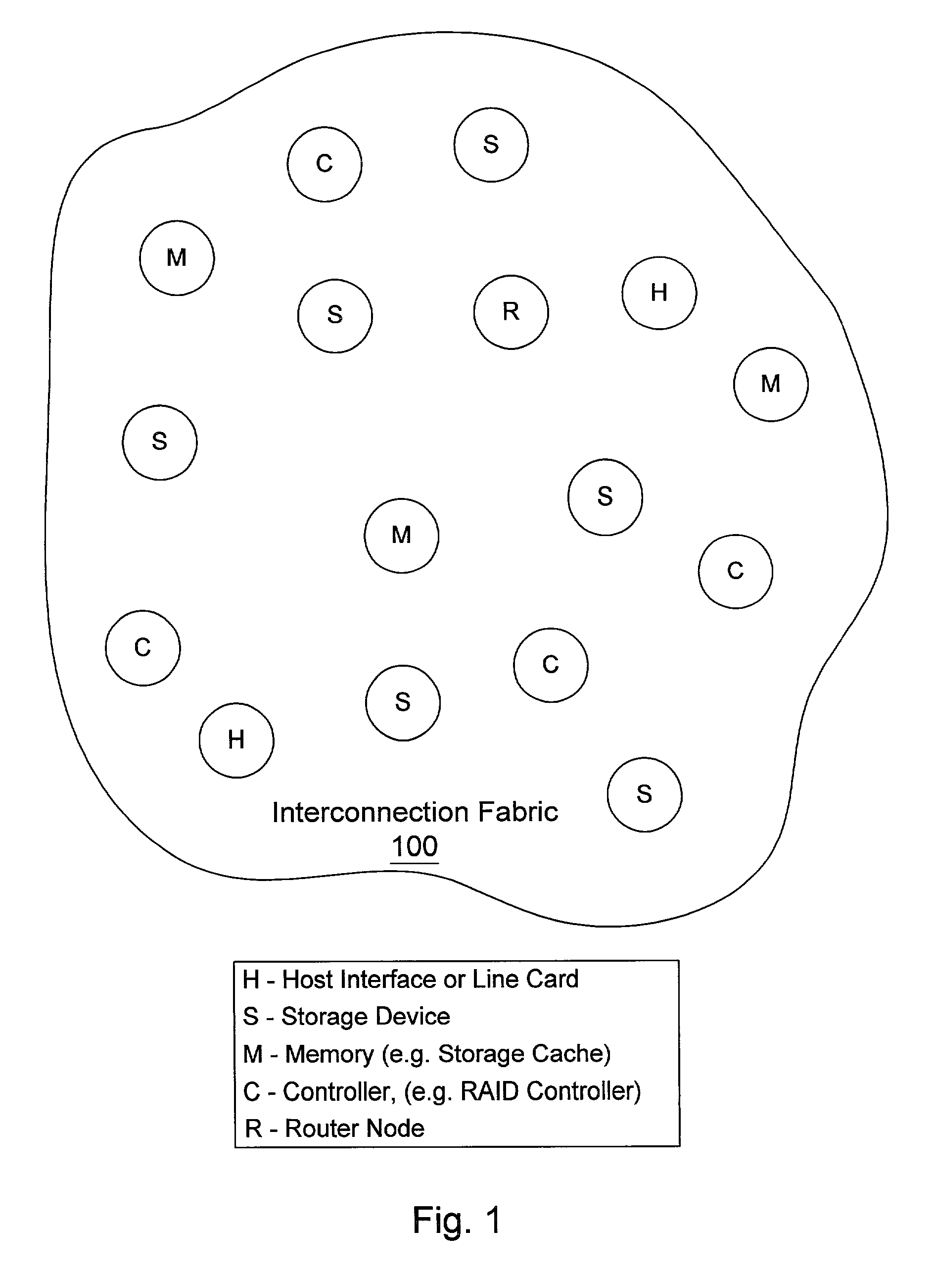
[0040] Turning now to FIG. 1, a diagram of one embodiment of an interconnection fabric using multiple independent paths is shown. An interconnection fabric 100 is shown with several nodes. Each node may support one or more different types of devices in a storage system. The nodes are labeled with the letters C, H, M, R and S. A node with the letter C means the node may be configured to support a controller such as a Redundant Array of Inexpensive Disks (RAID) controller. A node with the letter H means the node may be configured with a ...


PUM


Abstract

Embodiments of a routing system are disclosed, including a method for routing a plurality of communications in a storage system. The storage system may include a plurality of nodes interconnected by an interconnection fabric that provides multiple independent paths between each source node and each destination node. Some nodes may be connected to one or more disk drives. The method may include receiving a communication to be sent from a source node to a destination node, selecting a communication path from the multiple independent paths between the source and destination nodes, and sending the communication on the selected communication path. This process may be repeated so that multiple communications may be sent. Each communication path is systematically selected at least occasionally to send at least one of the communications to prevent any path from having undetected problems.

Description

[0001] 1. Field of the Invention[0002] This invention relates generally to the field of computer systems and, more particularly, to communication routing or switching within interconnection fabrics for computer storage networks.[0003] 2. Description of the Related Art[0004] Computer systems are placing an ever-increasing demand on data storage systems. In many of the data storage systems in use today, data storage arrays are used. The interconnection solutions for many large storage arrays are based on bus architectures such as small computer system interconnect (SCSI) or fibre channel (FC). In these architectures, multiple storage devices such as disks may share a single set of wires, or a loop in the case of FC, for data transfers.[0005] Such architectures may be limited in terms of performance and fault tolerance. Since all the devices share a common set of wires, only one data transfer may take place at any given time, regardless of whether or not all the devices have data ready...

Claims


Application Information

Patent Timeline
Patent Type & Authority Applications(United States)
IPC IPC(8): H04L12/56
CPCH04L45/00H04L45/22H04L45/24H04L45/28
Inventor LEE, WHAY S.RETTBERG, RANDALL D.
Owner ORACLE INT CORP
Why Eureka
Try Eureka