Natural robot control

a robot control and robot technology, applied in the field of natural robot control, can solve the problems of overextending the cut or causing the cut to be too shor

Inactive Publication Date: 2003-02-13
SIMMONS JOHN CASTLE
View PDF0 Cites 164 Cited by
  • Summary
  • Abstract
  • Description
  • Claims
  • Application Information

AI Technical Summary

Benefits of technology

0002] The current invention allows a human operator to perform delicate or indelicate tasks with great dexterity remotely with broad multiple and synchronized simultaneous sensory interaction as if the user were actually there. This includes the accurate, full-body interactive, real time perceptions and control of weight, distance, inner ear balance, motion/inertia, speed, pressure, vibration, impact, resistance to action, sound and a true, position responsive visual interface as if his body were actually in the remote location. Unlike the existing screen displays that reflect a camera view of a remote location dislocated from the actual perspective of the user's body attitude or user action, the visual perspective of the current invention is responsive to the exact pitch, roll and yaw of the user's head and body as well as to the relative velocity of the full body. Thus the user actually looks down where his hands really are, sees hands and remote objects in them just as if he were there. Further, the user is not holding a local tool that is interfaced to a singular remote tool that emulates the motion of the local tool but, instead, the local user is actually holding empty air despite the fact that he sees and feels the weight, resistance and vibration of the tool in his hand. Guided naturally by visual, sound and other sensory interaction, the user's hands, arms and other limbs are acting in the remote world using any tool that can be found at the remote site or just using the hands and other body parts alone. Thus the current invention is not limited to special tools, limited work areas, narrow vis

Problems solved by technology

Further, the user is not holding a local tool that is interfaced to a singular remote tool that emulates the motion of the local tool but, instead, the local user is actually holding empty air despite the fact that he sees and feels t

Method used


Image

  • Natural robot control
  • Natural robot control
  • Natural robot control

Examples


case 1

[0123] If P3=P2.

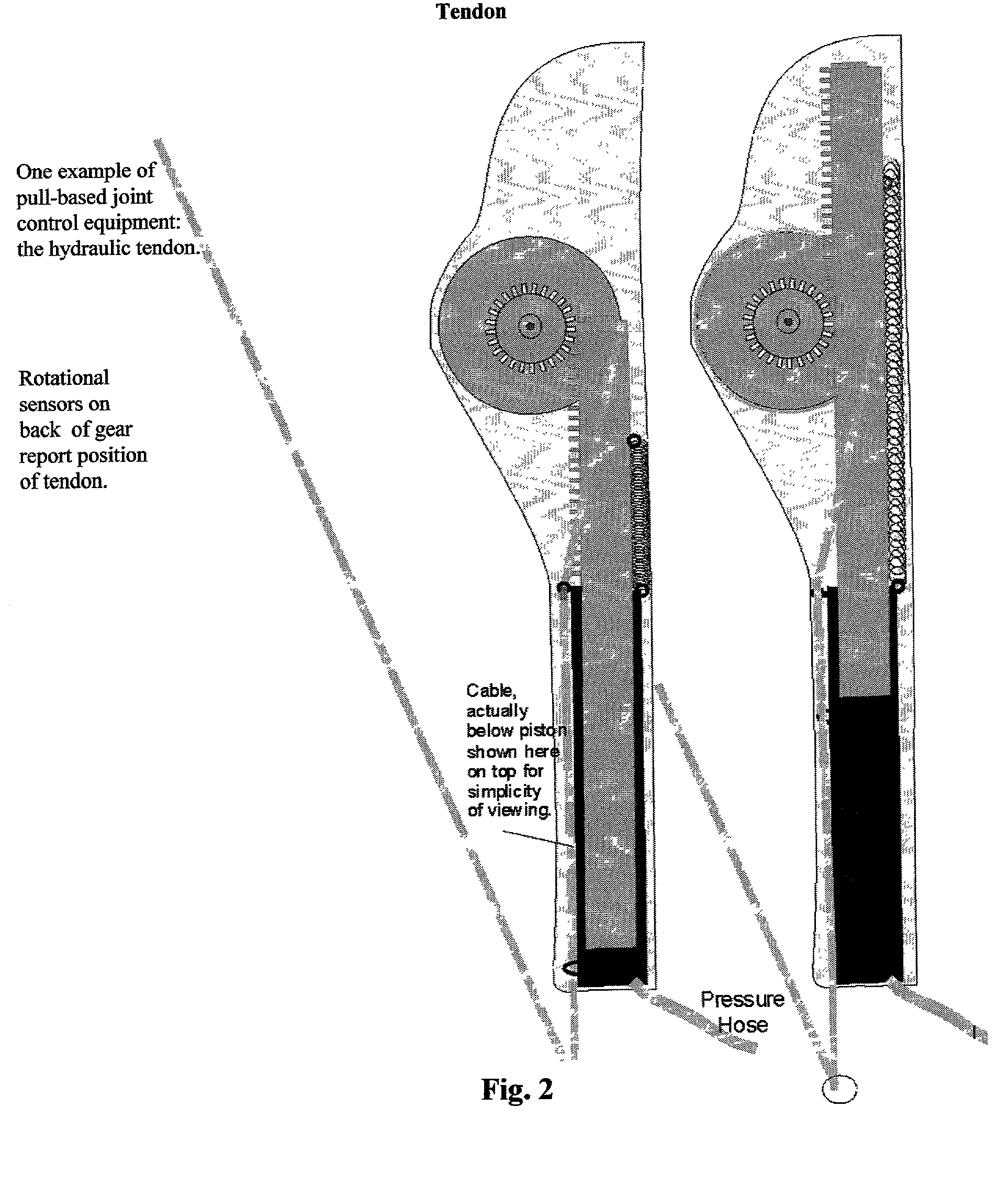
[0124] Either no motion occurred since the last end of phase IV or it was self-negated by the movement of the local during phase 1,2 and 3, if any. No physical adjustment is necessary. However, resistance pressure is another matter. In this embodiment the remote actuator increases angle by increasing hydraulic pressure and maintains position by continued but minimal required positive pressure after position is achieved. If the remote actuator had to exert a force (which can be positive or negative--pressure or vacuum) of F2 to maintain position at the remote, the local would now at this instant assume a pressure of -1*F2 plus or minus special equipment adjustments (assuming a joint that is not controlled by offsetting actuators like the tendons below but is simply pushed or pulled by positive pressure or a vacuum).

[0125] Special equipment adjustments apply to most force measurements and will slightly increase or decrease the pressure adjustments given to accommodate...

case3

[0131] IfP2>=P3 and P3>=P1

[0132] Here the remote complies or even over-complies (usually for the sake of speed) with a local order to advance but the user's continued motion during phase 2 and 3 did not make up for it. If P2=P3, no adjustments will be necessary. Otherwise, while adjustments will be very minor, the local will now be further accelerated in its current direction of motion to the position P2 so the local user will be completely caught up and perfectly in sync with the remote. The resistance pressure will be applied. Again, the resistance will be the relative negative of F2 but, since over-compliance typically would not happen when the remote was encountering motion resistance, it can be a positive number reflecting the relative inertia (relative because it is comparative to that of the local) of the remote's motion and the lack of current resistance at the remote. The positional value forwarded to phase 1 programming logic is P2

[0133] Case 4: If P3>=P1 and. PI>=P2.

[0134...

case1

[0158] Pa1=Pa2=Pa3

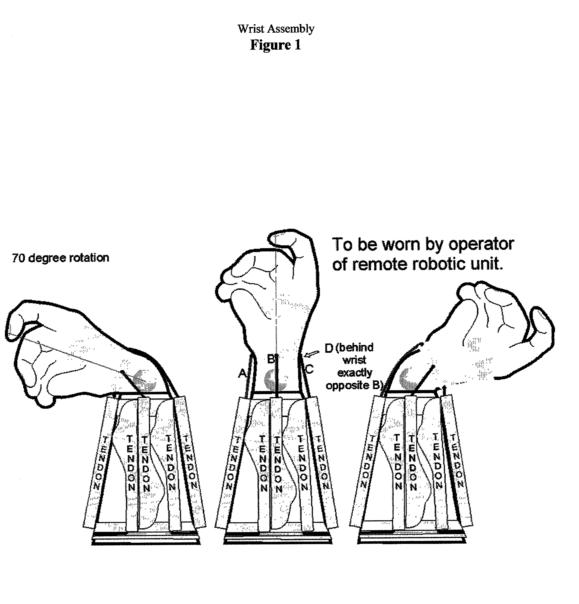
[0159] Nothing moved or, by the time we came back to phase IV, things were in this already synchronized state. No positional change is necessary. However, the maintenance pressure on this local tendon A is now based on the maintenance pressure on its opposite tendon (in this case Fc).

[0160] We say "based on "Fc above (instead of "precisely equal to") because, as mentioned above and assumed below, software adjustments to these figures may be made to accommodate both the weight and inertia of the equipment (to make it feel weightless) and also to provide tension between opposing tendons even when no work is being done to keep them firmly in position without precision killing slack. There are at least two types of such adjustments:

[0161] 1. Static Offsetting Adjustments: A fixed minimum offsetting pressure (always a positive number in this pulling tendon based embodiment because the pressure that creates that "negative" pulling pressure is positive) would always be i...


PUM


Abstract

An apparatus and process for controlling a remote robot responsive to the integrated sensory perceptions, natural body movements, inertia and gravitation of an operator/user who is himself responding to a three dimensional virtual world of visual and sensory conditions responsive to the environment at the remote site where the robot is operating. The user requires no training, special commands or devices to direct the robot because the user has the perception of actually being at the remote location, handling remote objects he sees and feels in his hands, walking, climbing, viewing and feeling the remote world.

Description

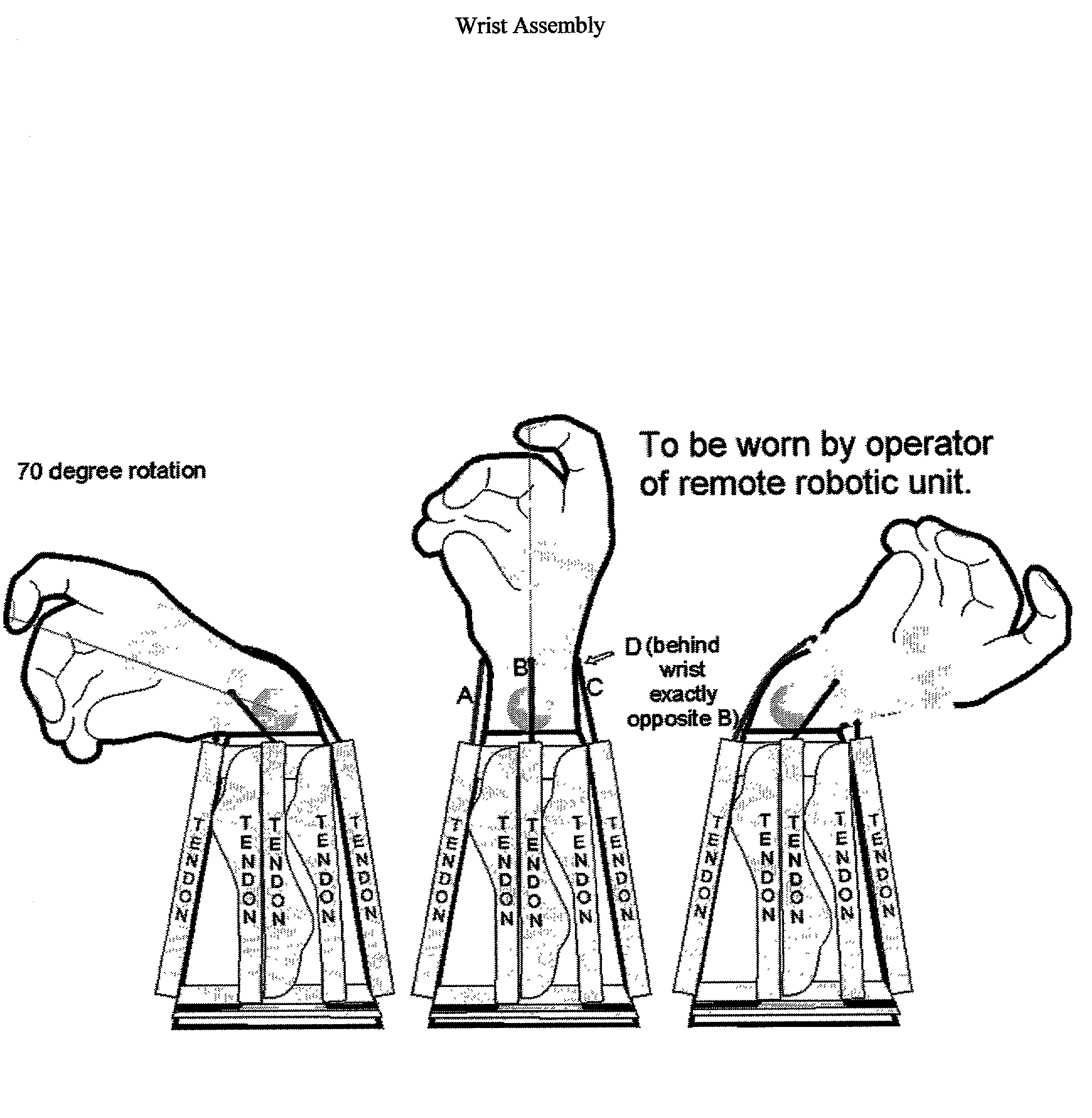
[0001] Throughout history, man has always wanted to be somewhere he is not. Even today, people struggle with the problems that can only be solved by "being there" even when "being there" involves substantial danger (ex: bomb squads) or great inconvenience (travel). Existing robotics equipment and processes provide means for a user to direct the actions of remote actuators. Salcudean et al U.S. Pat. No. 5,382,885 issued January 1995 discloses a local tool that can be manipulated causing an operatively identical remote tool such as a scalpel to follow suit additionally providing responsive and even leveraged pressure back on the tool the user grasps in his hand. Response feedback is limited to the moment of the tool itself, not the user's fingers, hand, wrist, etc. Slotine et al U.S. Pat. No. 5,266,875 issued May 1991 provides feedback in a joystick and additionally provides a transmission delay effect softening process the latter of which can be optionally applicable to ancillary fea...

Claims


Application Information

Patent Timeline
IPC IPC(8): B25J9/00B25J9/16G06F3/00G06F3/01
CPCB25J9/0006B25J9/1689G05B2219/40136G05B2219/40144G06F3/011
Inventor SIMMONS, JOHN CASTLE
Owner SIMMONS JOHN CASTLE
Why Eureka
Try Eureka