Method for precision bending of sheet of materials, slit sheets fabrication process

Inactive Publication Date: 2003-02-27
IND ORIGAMI INC CA US
View PDF6 Cites 134 Cited by
  • Summary
  • Abstract
  • Description
  • Claims
  • Application Information

AI Technical Summary

Benefits of technology

0049] In both embodiments, a virtual fulcrum is provided upon bending that can be positioned precisely on the bend line to cause bending of the bending straps or webs more precisely along the bend line. The detailed concept of the virtual fulcrum is described in below in the BEST

Problems solved by technology

A commonly encountered problem in connection with bending sheet material is that the locations of the bends are difficult to control because of bending tolerance variations and the accumulation of tolerance errors.
The second bend, however, often is positioned based upon the first bend and accordingly the tolerance errors can accumulate.
Since there can be three or more bends which are involved to create the chassis or enclosure for the electronic components, the effect of cumulative tolerance errors in bending can be significant.
Nevertheless, even a grooving-based or slitting-based bending of sheet material has its problems.
Moreover, the grooves or slits do not necessarily produce bending of webs 27 directly along bend line 25, and the grooving process is slow and inconsistent, particularly when milling or point cutting V-shaped grooves.
Grooving, therefore, is not in widespread commercial use.
Failure of the structure will occur at lower force levels than if a non-slitting or non-grooving bending process were used.
The architects of this sculpture recognized that the resulting bend is not structurally strong, and they have incorporated partially hidden beams welded into the sculpture in the inner vertices of each of the stitched bends.
Another problem inherent in the slitting scheme of FIGS. 2-2B is that the strap width cannot be varied independently of the distance between slits and the strap width cannot be less than the material thickness without stressing the straps to the extreme.
This limits the flexibility in designs for structural loading of the straps.
The sheet slitting configuration of FIGS. 2-2B, therefore, can be employed for decorative bends, but it is not well suited for bends which are required to provide significant structural support.
Again, the bent sheet components were not designed for, or capable of, bearing significant unsupported loads along the bends.
In most of these prior art bending systems, however, the bend forming technique greatly weakens the resulting structure, or precision bends are not capable of being formed, or bending occurs by crushing the material on one side of the bend.
Moreover, when slitting is used i

Method used


Image

  • Method for precision bending of sheet of materials, slit sheets fabrication process
  • Method for precision bending of sheet of materials, slit sheets fabrication process
  • Method for precision bending of sheet of materials, slit sheets fabrication process

Examples


second embodiment

[0088] It has been found that the embodiment of FIGS. 3-5C'" is best suited for use with relatively ductile sheet materials. As the material becomes harder and less ductile, FIGS. 6 to 11 is preferred

[0089] In the embodiment of the present invention shown in FIGS. 6-8B a slitting configuration is employed which tucks or clamps the sheet material into interengaged relation on both sides of the slits, and also reduces bending strap plastic deformation and the residual stress in the straps. Moreover, this embodiment also allows the strap width to be varied independently of the jog distance.

[0090] A bending strap which is oblique to the bend line is employed, which allows the strap length to be increased, as compared to the shorter bending straps of FIGS. 3-5C'". Plastic deformation also is accomplished in part by twisting, rather than purely by bending, as in FIGS. 3-5C'", but the amount of twisting is greatly reduced, as compared to the parallel straps of FIGS. 2-2B. Moreover, the mat...

first embodiment

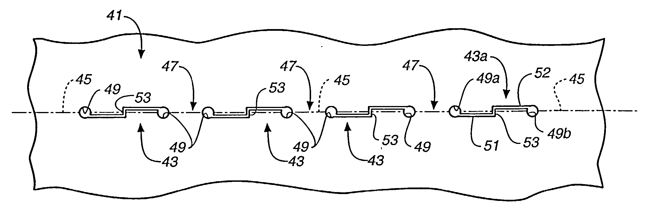
[0095] As was the case for the first embodiment, the slit kerfs preferably have a width dimension producing interengagement of sheet material on opposite sides of the slits during bending. Thus, slits 243 can be made with a knife and have essentially a zero kerf, or they can have a greater kerf which still produces interengagement, depending upon the thickness of the sheet being bent. As was the case for the embodiment of FIGS. 3-5C'", a tab portion 253 extends across bend line 245 to slit 243. Tab 253 slides or rides up a face 255 of sheet material defined by the opposite side of slits 243 if the kerf width, relative to the thickness of the material, is not so large as to prevent contact between the two SIDES OF THE SLIT during bending. It is possible to have the kerf width and position such that contact between the tab portion 253 and the face 255 does not occur and still have some of the advantages of oblique bending straps, but in such instances there are no actual fulcrums for ...


PUM

PropertyMeasurementUnit
Angleaaaaaaaaaa
Thicknessaaaaaaaaaa
Angleaaaaaaaaaa

Abstract

A method for precision bending of a sheet of material (41, 241, 341, 441) along a bend line (45, 245, 345, 445) and the resulting sheet are disclosed. A method includes a step of forming longitudinally extending slits (43, 243, 343, 443) through the sheet of material in axially spaced relation to produce precise bending of the sheet (41, 241, 341, 441) along the bend line (45, 245, 345, 445) with edges (257, 457) engaged and supported on faces (255, 455) of the sheet material on opposite sides of the slits. The edge-to-face contact produces bending along a virtual fulcrum position in superimposed relation to the bend line (45, 245, 345, 445). Several slit embodiments (43, 243, 343, 443) suitable for producing edge-to-face engagement support and precise bending are disclosed, as is the use of the slit sheets to enhance various fabrication techniques.

Description

[0001] This application is a Continuation-in-Part Application based upon a copending parent application, Ser. No. 09 / 640,267, filed Aug. 17, 2000, and entitled METHOD FOR PRECISION BENDING OF A SHEET OF MATERIAL AND SLIT SHEET THEREFOR.[0002] The present invention relates, in general, to the bending of sheets of material and the formation of structures therefrom, and more particularly, relates to slitting sheet material in order to enable bending and to the use of such slit sheet material for rapid two-dimension to three-dimensional fabrication of high strength multi-component structures or assemblies.[0003] A commonly encountered problem in connection with bending sheet material is that the locations of the bends are difficult to control because of bending tolerance variations and the accumulation of tolerance errors. For example, in the formation of the housings for electronic equipment, sheet metal is bent along a first bend line within certain tolerances. The second bend, howeve...

Claims


Application Information

Patent Timeline
IPC IPC(8): B21D28/26B21B5/00B21D5/00B21D5/02B21D11/20B21D28/00B21D43/28B32B1/08B32B3/10B32B5/12B32B27/04B65HB65H1/00D04H1/00D04H3/00D04H5/02E04C2/08
CPCB21D28/10B21D35/00B21D39/037B21D47/01B21D51/52B29C53/063Y10T428/12368B21D11/08Y10T428/24273Y10T428/24314Y10T428/139Y10T428/12361E04C2/08B33Y80/00Y10T83/04B21D28/00B32B3/10B21D5/00
Inventor DURNEY, MAX W.PENDLEY, ALAN D.
Owner IND ORIGAMI INC CA US
Why Eureka
Try Eureka