

Method of forming molded articles of amorphous alloy with high elastic limit
- Summary
- Abstract
- Description
- Claims
- Application Information
AI Technical Summary
Benefits of technology
Problems solved by technology
Method used
Image

Examples
Embodiment Construction
[0029] This invention is directed to a method of forming molded articles of bulk-solidifying amorphous alloys around the glass transition range, which preserves the high elastic limit of the bulk solidifying amorphous alloy upon the completion of molding process.
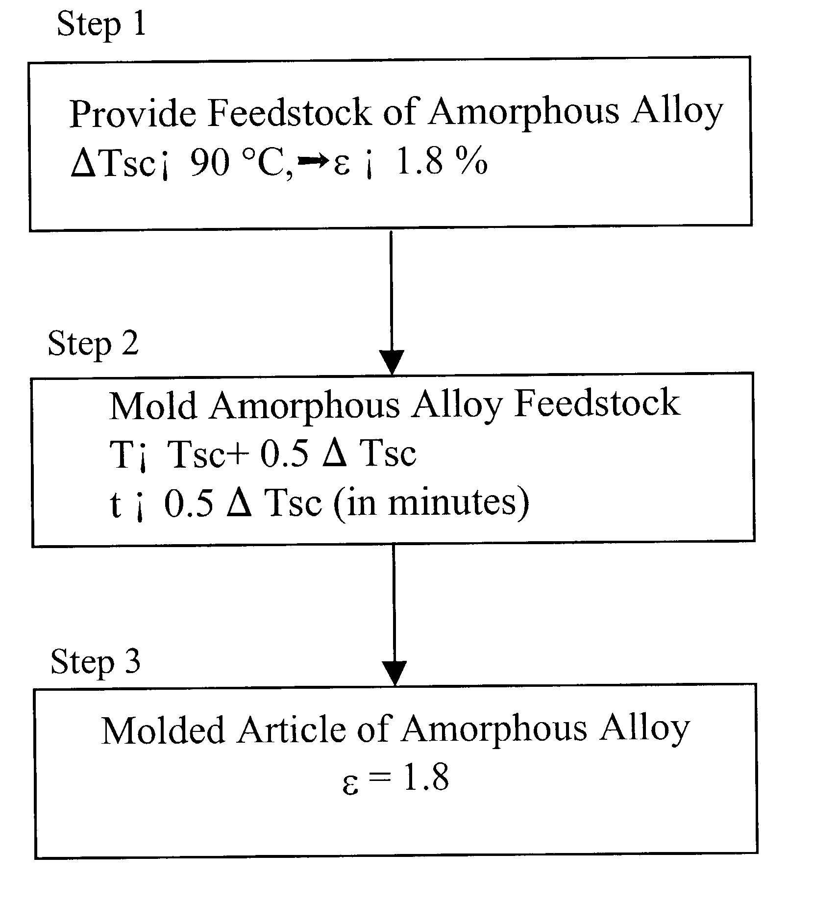
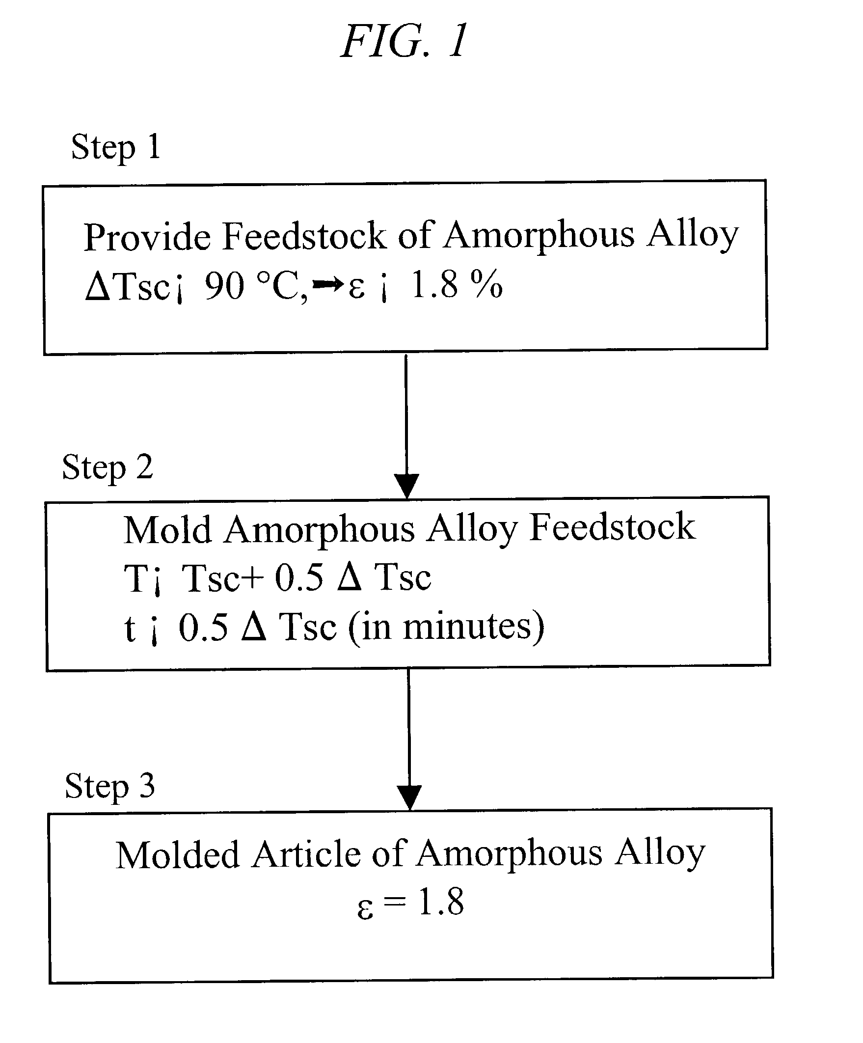
[0030] In one embodiment of the invention, shown schematically in FIG. 1, a feedstock of bulk solidifying amorphous alloy is provided at Step 1. At Step 2, the provided feedstock of bulk solidifying amorphous alloy is molded around the glass transition range such that the final product maintains the high elastic limit of the bulk solidifying amorphous alloy feedstock. By controlling the time and temperature of the molding, upon the completion of forming process, at Step 3, the molded articles according to the current invention retains an elastic limit of at least 1.2%, and preferably an elastic limit of at least 1.8%, and most preferably an elastic limit of at least of 1.8% plus a bend ductility of at least 1.0%. Herein, the...
PUM
| Property | Measurement | Unit |
|---|---|---|
| Fraction | aaaaa | aaaaa |
| Fraction | aaaaa | aaaaa |
| Fraction | aaaaa | aaaaa |
Abstract
Description
Claims
Application Information