

Refrigerant cycle system having discharge function of gas refrigerant in receiver
a technology of refrigerant cycle and discharge structure, which is applied in the direction of subcoolers, machine operation modes, lighting and heating apparatus, etc., can solve the problems of restricted refrigerant flow from the upper side of the receiver, and the insufficient cooling of the upper space of the receiver
- Summary
- Abstract
- Description
- Claims
- Application Information
AI Technical Summary
Benefits of technology
Problems solved by technology
Method used
Image

Examples
first embodiment
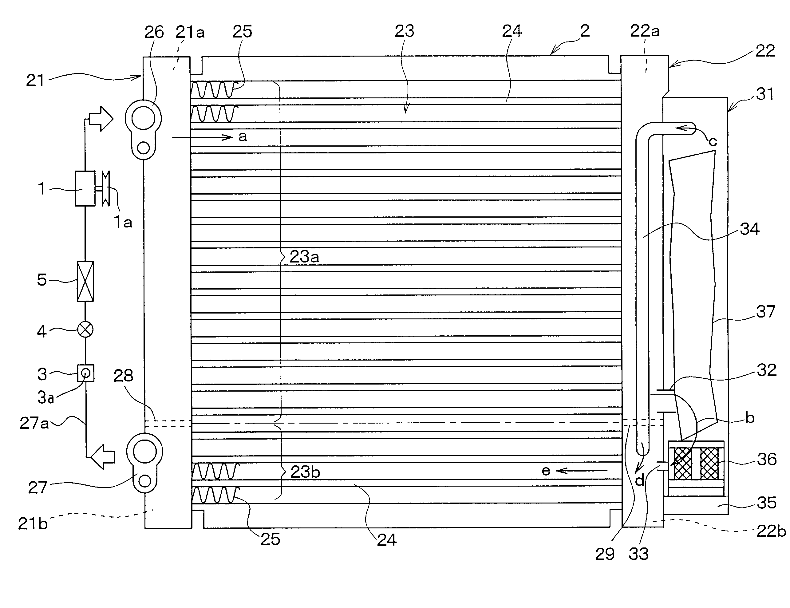
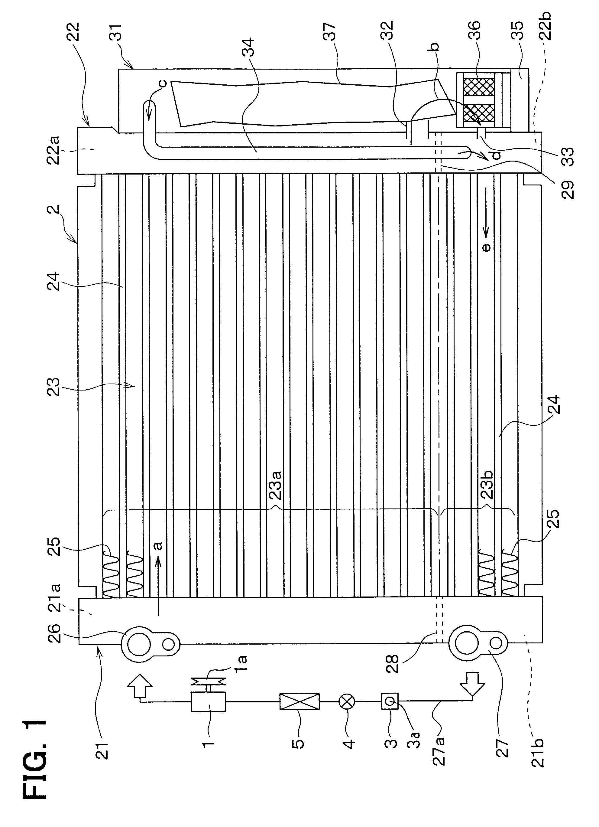
[0026] A first preferred embodiment of the present invention will be now described with reference to FIGS. 1-4. In the first embodiment, the present invention is typically applied to a refrigerant cycle system for a vehicle air conditioner. As shown in FIG. 1, the refrigerant cycle system of the vehicle air conditioner includes a refrigerant compressor 1, a receiver-integrated refrigerant condenser 2, a sight glass 3, an expansion valve 4, and a refrigerant evaporator 5. All the components of the refrigerant cycle system are serially connected by a metal pipe or a rubber pipe to form a closed circuit.
[0027] The compressor 1 is connected to an engine disposed within an engine compartment through a belt and an electromagnetic clutch 1a. When the rotation power of the engine is transmitted to the compressor 1 through the electromagnetic clutch 1a, the compressor 1 compresses gas refrigerant sucked therein from the evaporator 5 and then discharges high-pressure high-temperature gas refr...
second embodiment
[0057] According to the present invention, because the pressure difference is generated between both the ends of the gas bypass pipe 34 due to the pressure loss in the super-cooling portion 23b, it is unnecessary for the second communication hole 33 to be used as the pressure-loss generation portion. Accordingly, the opening area of the second communication hole 33 can be freely set.
[0058] In the second embodiment, because the super-cooling portion 23b is used as the pressure-loss generation portion, the outlet end of the gas bypass pipe 34 can be connected to the high-pressure liquid refrigerant pipe 27a (see FIG. 1). Alternatively, the outlet end of the gas bypass pipe 34 can be connected to a low-pressure side refrigerant passage (e.g., a downstream side of the expansion valve 4), through a suitable throttle.
[0059] A third preferred embodiment of the present invention will be now described with reference to FIGS. 6A and 6B. In the above-described first and second embodiments of t...
third embodiment
[0060] As shown in FIGS. 6A and 6B, in the present invention, the connection plate 40 is inserted between the receiving unit 31 and the second header tank 22, to be connected to the receiving unit 31 and the second header tank 22 by a fastening member. Therefore, in an assembling step before a brazing of the receiver-integrated refrigerant condenser 2, the connection plate 40 is used for temporally fixing the receiving unit 31 and the second header tank 22.
[0061] As shown in FIG. 6B, the connection plate 40 is made of an aluminum alloy, and is formed into an elongated rectangular shape by pressing. In the pressing, the first communication hole 32 and the second communication hole 33 are opened in the connection plate 40, and a gas bypass passage 41 (third refrigerant passage) extending in a longitudinal direction (i.e., vertical direction) of the connection plate 40 is provided in the connection plate 40. A lower end portion of the gas bypass passage 41 is bent by a right angle to c...
PUM
 Abstract
Description
Claims
Application Information