
Objective lens system for microscope

a technology of objective lens and microscope, which is applied in the field of microscope objective lens system, can solve the problems of deteriorating image quality, above described conventional and the objective lens system is not satisfactory

Inactive Publication Date: 2003-03-20
CENT FOR THE ADVANCEMENT OF HEALTH & BIOSCI +2
View PDF2 Cites 21 Cited by
  • Summary
  • Abstract
  • Description
  • Claims
  • Application Information

AI Technical Summary

Problems solved by technology

Autofluorescence of glass material used as a lens element in the objective lens system is a source of undesirable background light that degrades the image quality.
However, comparing these to the highest class microscope objective lens system, a so-called plan-apochromat objective in which the numerical aperture is extremely large and the aberrations, particularly the image curvature and longitudinal chromatic aberration including the secondary spectrum are highly corrected, the above described conventional objective lens systems are not satisfactory from the viewpoint of the basic requirements (A) through (D) for a microscope objective lens system.
The objective lens system disclosed in publication No.1 is small in numerical aperture and not satisfactorily corrected in flatness of the image.
The objective lens system disclosed in publication No.3 is large enough in numerical aperture and well corrected in the longitudinal chromatic aberration but the flatness of the image is not satisfactorily corrected.
Among the objective lens systems disclosed in publication No. 5, the one having a magnification power of 100.times. is small in N.A. and unsatisfactorily corrected in the flatness of the image, whereas the other one having a magnification power of 40.times. is unsatisfactorily corrected in the flatness of the image.

Method used


Image

  • Objective lens system for microscope
  • Objective lens system for microscope
  • Objective lens system for microscope

Examples


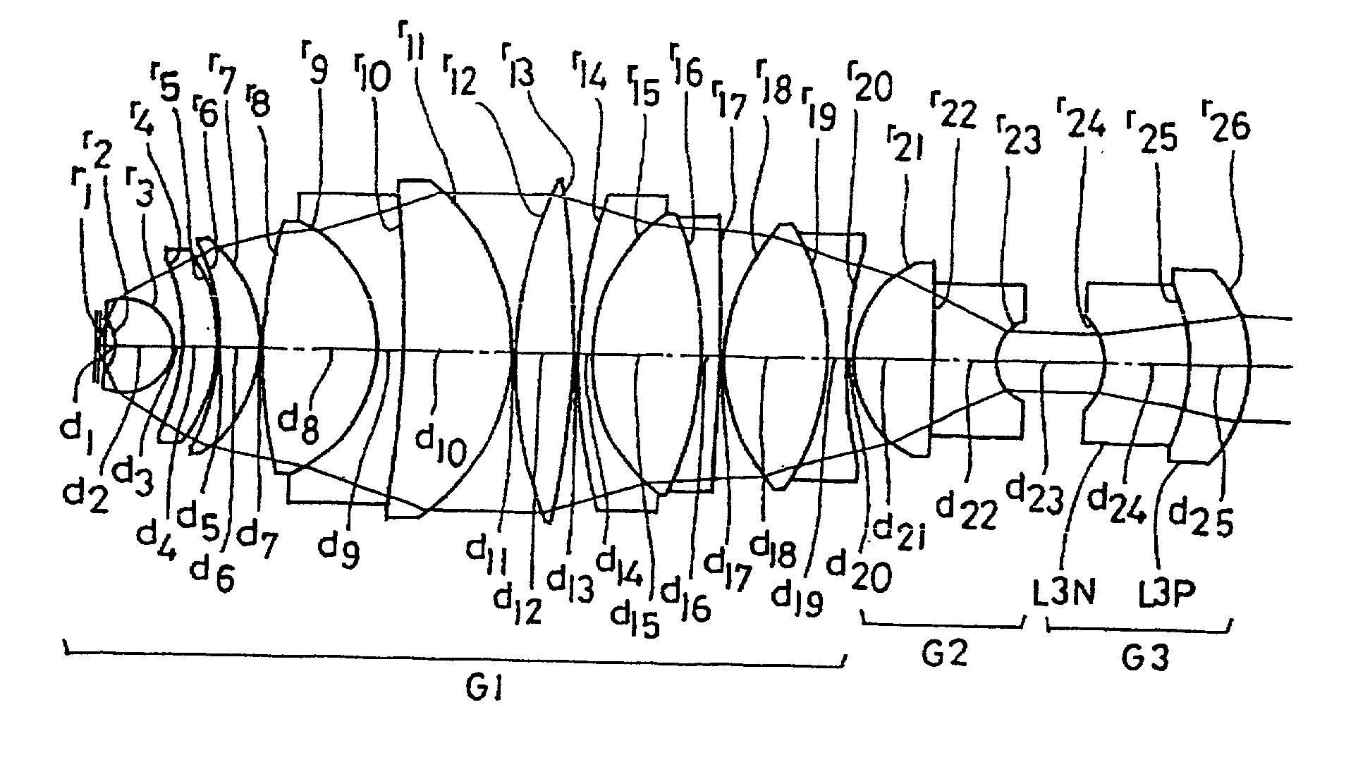
numerical example 1

[0077] Magnification power 100.times., N.A. 1.45, Field Number 26.5, W.D. 0.15, Total length 59.36

1 r1 = .infin. d1 = 0.5136 n1 = 1.51633 .nu.1 = 64.15 r2 = -1.9022 d2 = 2.7702 n2 = 1.75500 .nu.2 = 52.32 r3 = -2.3778 d3 = 0.2767 r4 = -11.0234 d4 = 1.6727 n3 = 1.49700 .nu.3 = 81.54 r5 = -8.3960 d5 = 0.1321 r6 = -11.5121 d6 = 2.0521 n4 = 1.49700 .nu.4 = 81.54 r7 = -6.7079 d7 = 0.1205 r8 = 24.2059 d8 = 5.8975 n5 = 1.43875 .nu.5 = 94.99 r9 = -6.8330 d9 = 1.2964 n6 = 1.74100 .nu.6 = 52.64 r10 = -61.2342 d10 = 5.6428 n7 = 1.43875 .nu.7 = 94.99 r11 = -10.0117 d11 = 0.2000 r12 = 20.1093 d12 = 3.0743 n8 = 1.43875 .nu.8 = 94.99 r13 = -41.8986 d13 = 0.2000 r14 = 25.0008 d14 = 0.7954 n9 = 1.75500 .nu.9 = 52.32 r15 = 8.6458 d15 = 5.8479 n10 = 1.43875 .nu.10 = 94.99 r16 = -15.8080 d16 = 0.8000 n11 = 1.75500 .nu.11 = 52.32 r17 = -103.4152 d17 = 0.2000 r18 = 9.3938 d18 = 5.4070 n12 = 1.43875 .nu.12 = 94.99 r19 = -11.5986 d19 = 0.9404 n13 = 1.49831 .nu.13 = 65.03 r20 = 19.4800 d20 = 0.3650 r21 = 5.2...

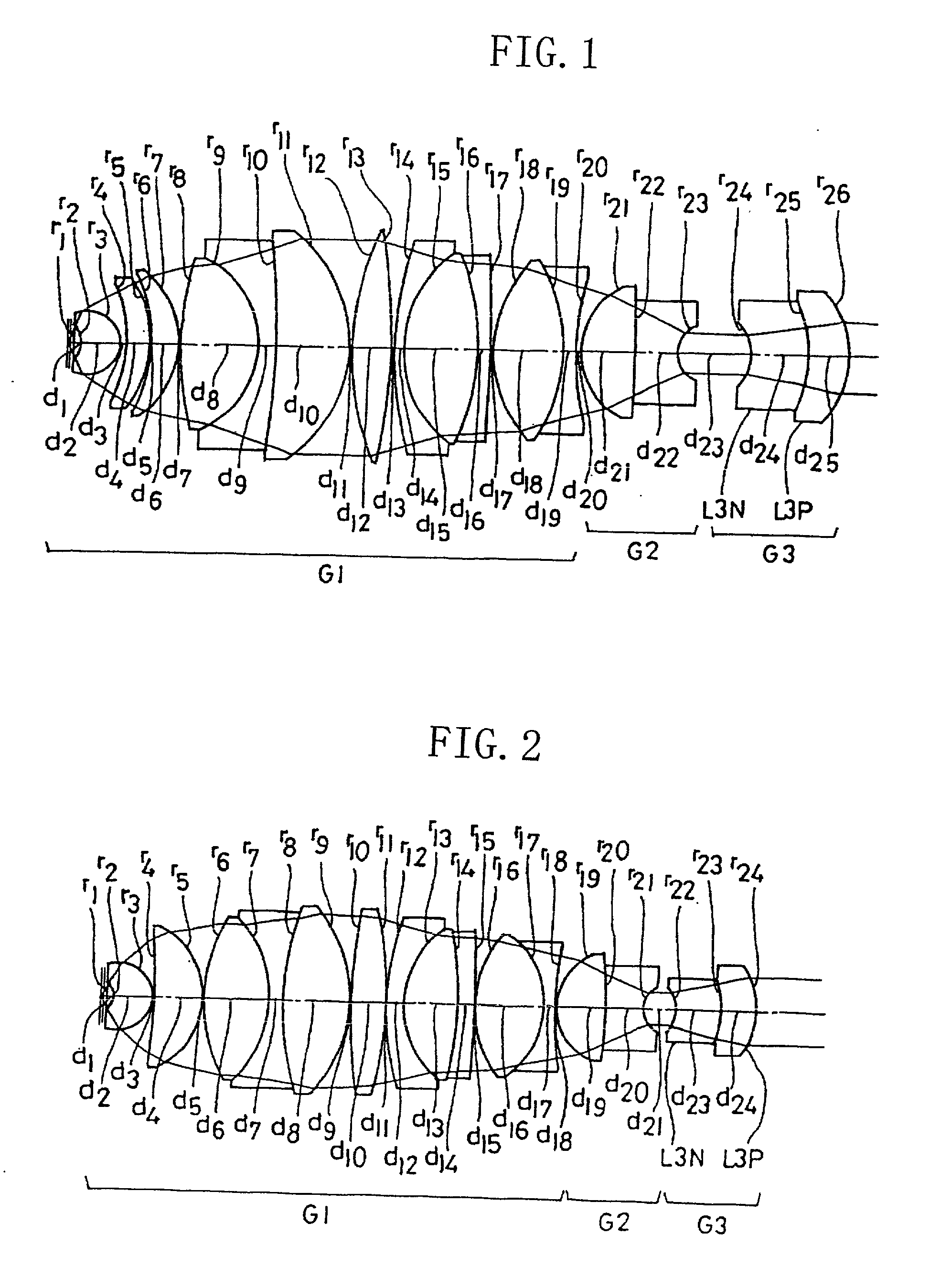
numerical example 2

[0078] Magnification power 100.times., N.A. 1.4, Field number 26.5, W.D. 0.15, Total length 49.56

2 r1 = .infin. d1 = 0.5000 n1 = 1.51633 .nu.1 = 64.15 r2 = -1.5660 d2 = 2.8050 n2 = 1.75500 .nu.2 = 52.32 r3 = -2.4571 d3 = 0.1000 r4 = -41.4271 d4 = 3.6613 n3 = 1.43875 .nu.3 = 94.99 r5 = -5.7417 d5 = 0.1000 r6 = 11.9388 d6 = 4.9598 n4 = 1.43875 .nu.4 = 94.99 r7 = -8.2962 d7 = 1.0240 n5 = 1.74100 .nu.5 = 52.64 r8 = 20.1050 d8 = 5.0349 n6 = 1.43875 .nu.6 = 94.99 r9 = -10.0738 d9 = 0.1000 r10 = 37.3858 d10 = 2.6776 n7 = 1.43875 .nu.7 = 94.99 r11 = -27.4359 d11 = 0.0996 r12 = 20.1201 d12 = 1.3120 n8 = 1.75500 .nu.8 = 52.32 r13 = 6.7987 d13 = 4.0920 n9 = 1.43875 .nu.9 = 94.99 r14 = -24.5755 d14 = 1.2120 n10 = 1.75500 .nu.10 = 52.32 r15 = -140.3679 d15 = 0.1000 r16 = 8.5944 d16 = 5.2361 n11 = 1.43875 .nu.11 = 94.99 r17 = -6.3117 d17 = 0.7607 n12 = 1.51633 .nu.12 = 64.15 r18 = 23.5004 d18 = 0.0998 r19 = 4.1449 d19 = 3.8192 n13 = 1.43875 .nu.13 = 94.99 r20 = -29.6373 d20 = 2.8474 n14 = 1.74100...

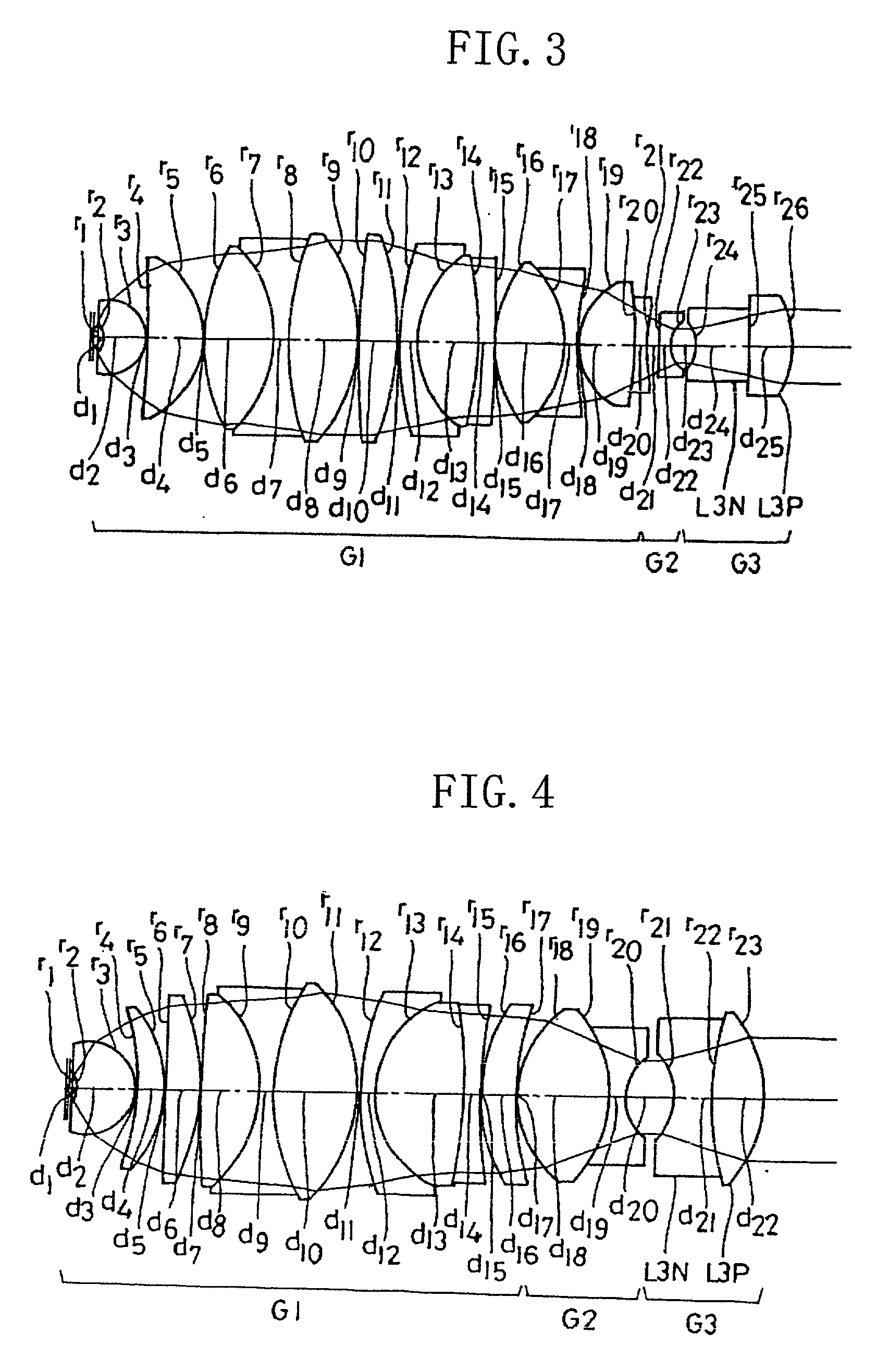
numerical example 3

[0079] Magnification power 100.times., N.A. 1.4, Field number 26.5, W.D. 0.15, Total length 49.36

3 r1 = .infin. d1 = 0.5000 n1 = 1.51633 .nu.1 = 64.15 r2 = -1.5660 d2 = 2.8000 n2 = 1.75500 .nu.2 = 52.32 r3 = -2.4628 d3 = 0.1081 r4 = -70.9829 d4 = 3.7327 n3 = 1.43875 .nu.3 = 94.99 r5 = -5.9260 d5 = 0.1000 r6 = 12.2913 d6 = 4.8110 n4 = 1.43875 .nu.4 = 94.99 r7 = -8.4952 d7 = 1.0000 n5 = 1.74100 .nu.5 = 52.64 r8 = 19.1643 d8 = 4.7990 n6 = 1.43875 .nu.6 = 94.99 r9 = -10.8485 d9 = 0.1000 r10 = 50.2046 d10 = 2.7796 n7 = 1.43875 .nu.7 = 94.99 r11 = -18.3157 d11 = 0.1994 r12 = 20.7027 d12 = 1.2952 n8 = 1.74100 .nu.8 = 52.64 r13 = 6.7728 d13 = 4.1862 n9 = 1.43875 .nu.9 = 94.99 r14 = -25.6719 d14 = 1.1839 n10 = 1.74100 .nu.10 = 52.64 r15 = -254.5610 d15 = 0.0951 r16 = 8.7339 d16 = 4.9518 n11 = 1.43875 .nu.11 = 94.99 r17 = -6.7842 d17 = 0.8000 n12 = 1.51633 .nu.12 = 64.15 r18 = 21.1248 d18 = 0.1000 r19 = 4.5000 d19 = 4.0100 n13 = 1.49700 .nu.13 = 81.54 r20 = -25.7035 d20 = 0.9191 n14 = 1.61340...


PUM


Abstract

An microscope objective lens system comprises a first lens unit including a plurality of cemented lens components and converging light coming from an object, a second lens unit including a negative lens component having a strong concave surface on the image side, and a third lens unit including a cemented doublet composed of a negative lens element having a concave surface on the object side and a positive lens element, wherein the objective lens system satisfies the following conditions:1.65<=nd<=1.825<=nud<=41T360>=0.5wherein nd and nud are refractive index at the Fraunhofer d-line and the Abbe's number of the positive lens element in the third lens unit, respectively, and T360 is an internal transmittance except for a reflection loss at 360 nm for 10 mm thickness of material forming the positive lens element in the third lens unit.

Description

[0001] This application claims benefits of Japanese Patent Application No. 2001-208,783, filed on Jul. 10, 2001, in Japan, the contents of which are hereby incorporated by reference.[0002] 1. Field of the Invention[0003] This invention relates to a microscope objective lens system, more particularly to a microscope objective lens system qualified as an apochromat class objective lens system having a large numerical aperture (N.A.), high transmittance in the ultra-violet wavelength region, and a low autofluorescence which is suitable for a fluorescent observation.[0004] 2. Description of the Related Art[0005] Recently in the biological research field, the fluorescent microscopy has been widely used for observing specific substances in a living cell stained by fluorescent dyes because this way of observation is harmless to the cell.[0006] Generally speaking, the fluorescent microscopy is a manner of observation in which a specimen is irradiated with a light having a short wavelength f...

Claims


Application Information

Patent Timeline
Patent Type & Authority Applications(United States)
IPC IPC(8): G02B21/02
CPCG02B21/02
Inventor FUJIMOTO, YASUSHINISHIWAKI, DAISUKE
Owner CENT FOR THE ADVANCEMENT OF HEALTH & BIOSCI
Learn More