Fuel injection valve for internal combustion engines

a technology for internal combustion engines and fuel injection valves, which is applied in the direction of fuel injection apparatus, spraying apparatus, feeding system, etc., can solve the problems of valve seat deformation, valve member and valve seat deformation over time, and adversely affect the course of fuel injection and injection precision

Inactive Publication Date: 2003-03-27
ROBERT BOSCH GMBH
View PDF0 Cites 13 Cited by
  • Summary
  • Abstract
  • Description
  • Claims
  • Application Information

AI Technical Summary

Benefits of technology

[0004] The fuel injection valve of the invention having the characteristics of the body of claim 1 has the advantage over the prior art that the part of the valve member tip bearing the valve sealing face is embodied as a yielding annular collar, and as a result in the closing position of the valve member, the part bearing the valve sealing face, after an initial line contact, rests two-dimensionally on the valve seat. The outer edge of the annular collar defines a fixed seat diameter. Because of the increasing bearing area of the valve member on the valve seat, a relatively small pressure per unit of surface area exists in the region of the valve seat, leading to less wear in this region. Thus the seat diameter remains constant over the service life of the fuel injection valve.[0005] In an advantageous feature, the valve sealing face is partly undercut by the annular groove, so that the annular collar is embodied in liplike fashion to an increased extent, and the deformation work of the annular collar is reduced. By varying the shape of the annular groove, the yielding of the annular collar can be adapted to the applicable material comprising the valve member and the valve body.[0006] Further advantages and advantageous features of the subject of the invention can be learned from the drawing, description and claims.

Problems solved by technology

On the one hand, this produces good sealing of the pressure chamber from the injection openings, but on the other it raises the problem that because of the high pressure per unit of surface area, deformations of the valve member and valve seat occur over time.
As a result, the effective flow cross section of the fuel injection valve also changes, as does the size of the faces on the valve member that are subjected to pressure, which adversely affects the course of fuel injection and the injection precision.

Method used


Image

  • Fuel injection valve for internal combustion engines
  • Fuel injection valve for internal combustion engines
  • Fuel injection valve for internal combustion engines

Examples


Embodiment Construction

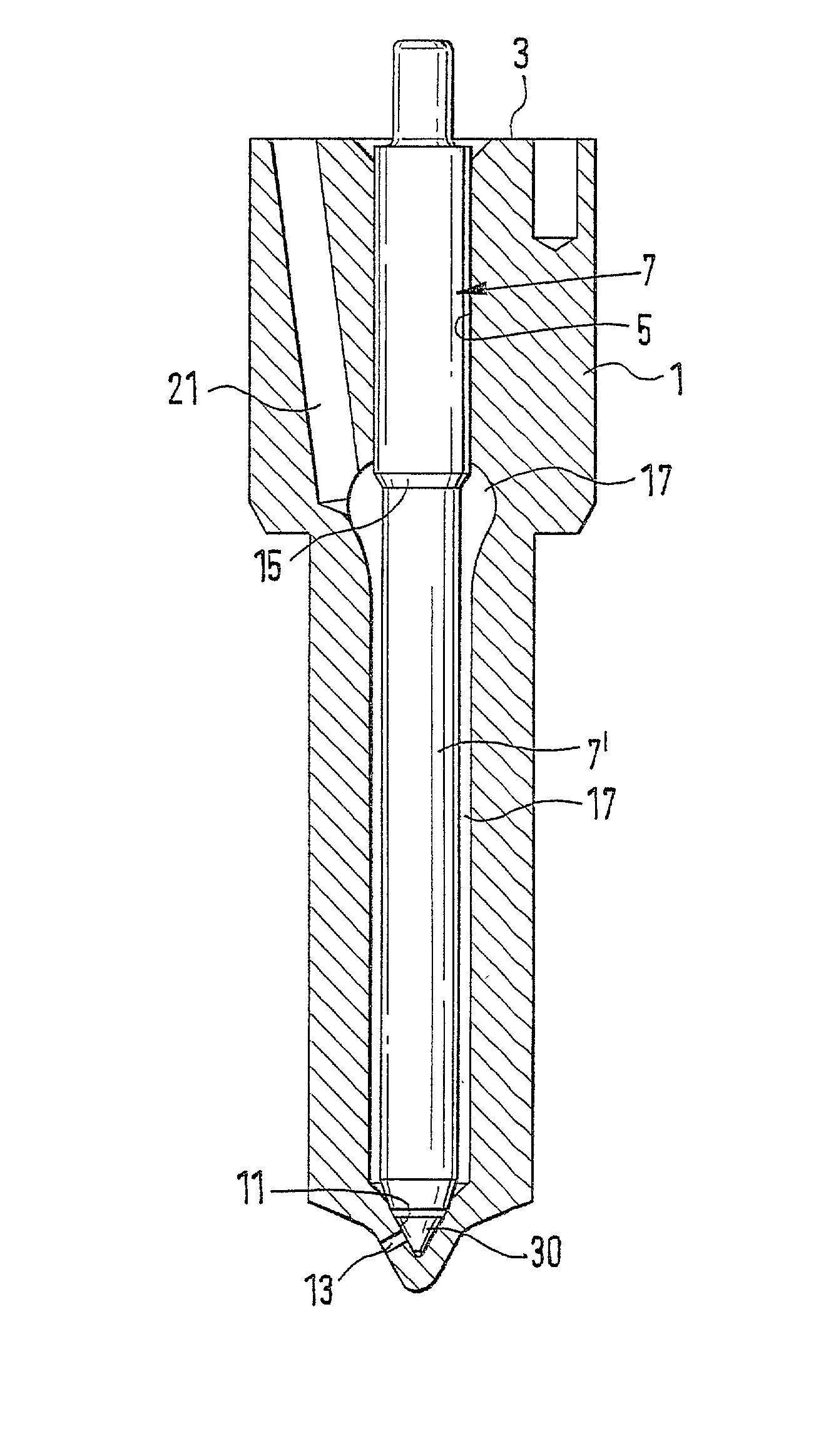
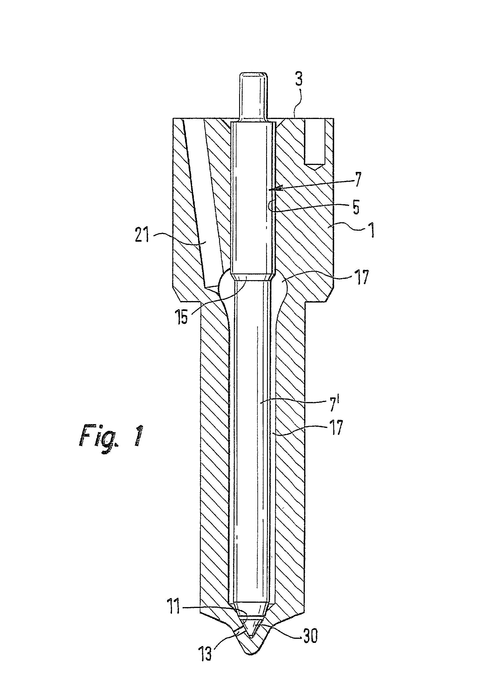
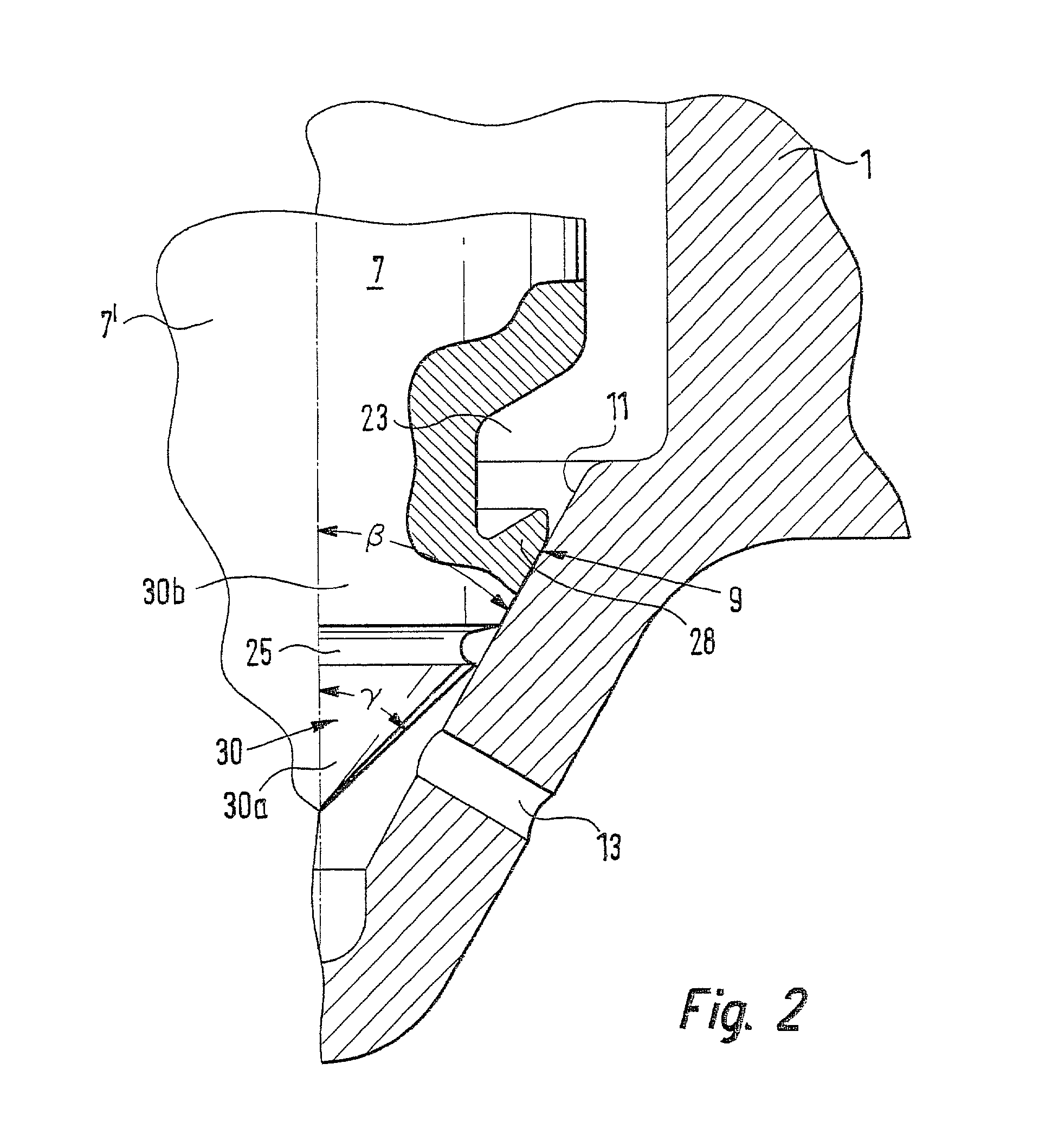
[0010] In FIG. 1, a longitudinal section is shown through an exemplary embodiment of the fuel injection valve of the invention. A valve body 1, whose end face remote from the combustion chamber, in the installed position, comes at least indirectly to rest on a valve retaining body, not shown in the drawing, has a bore 5 embodied as a blind bore. The bottom face is embodied as a valve seat 11 and is approximately conical, with a cone angle .alpha., and the inside diameter of the valve seat 11 decreases toward the combustion chamber. At least one injection opening 13, which connects the bore 5 to the combustion chamber, is embodied at the valve seat 11.

[0011] Disposed in the bore 5 is a piston like valve member 7, which is guided in the bore 5 with a larger-diameter portion, remote from the combustion chamber, and which toward the combustion chamber changes into a smaller-diameter valve member shaft 7', thereby forming a pressure shoulder 15. Between the wall of the bore 5 and the val...


PUM


Abstract

A fuel injection valve for internal combustion engines, having a valve body (1) in which in a bore (5), a valve member (7) is disposed to be axially movable counter to a closing force. On its end, the valve member (7) has a substantially conical valve member tip (30), which with a part of its jacket face that serves as a valve sealing face (9) comes to rest on a valve seat (11), embodied on the end toward the combustion chamber of the bore (5). At the transition from the valve member (7) to the valve member tip (30), an annular groove (23) is embodied, which undercuts the valve sealing face (11) in part and thereby forms an annular collar (28), which is resiliently yielding. The cone angle (beta) of the valve sealing face (9), in the open position of the valve member (7), is somewhat larger than the cone angle (alpha) of the valve seat (11), so that in the closing motion of the valve member (7) toward the valve seat (11), the annular collar (28) is first seated with the outer edge, embodied as a sealing edge (34) and is deformed inward by the further closing motion. The sealing edge (34) is thus not press-fitted into the valve seat (11), and as a result the seat diameter remains unchanged over the service life of the fuel injection valve (FIG. 2).

Description

PRIOR ART[0001] The invention is based on a fuel injection valve for internal combustion engines as generically defined by the preamble to claim 1. One such fuel injection valve is known from German Published, Nonexamined Patent Application DE 196 08 575. On the end toward the combustion chamber of the valve member, a substantially conical tip is formed. This tip is divided into two portions; the tip cone angle of the outer portion, toward the combustion chamber, is greater than that of the inner portion, toward the valve member. As a result, an encompassing annular edge is embodied as a sealing face on the jacket face of the valve member tip.[0002] The valve member is disposed in a bore, embodied as a blind bore, and the closed end, toward the combustion chamber, is embodied as a valve seat, which substantially has a conical shape. At least one injection opening is embodied in the valve seat and connects the interior of the valve with the combustion chamber, when the valve member i...

Claims


Application Information

Patent Timeline
Patent Type & Authority Applications(United States)
IPC IPC(8): F02M61/04F02M61/18
CPCF02M61/047F02M61/1873
Inventor BOECKING, FRIEDRICH
Owner ROBERT BOSCH GMBH
Why Eureka
Try Eureka