
Multi-zone resistive heater

a resistive heater and multi-zone technology, applied in the field of multi-zone resistive heaters, can solve the problems of difficult control of the temperature in the chamber, difficulty in uniform temperature, and single-zone resistive heaters not having the ability to compensate for differences

Inactive Publication Date: 2003-04-03
APPLIED MATERIALS INC
View PDF0 Cites 268 Cited by
  • Summary
  • Abstract
  • Description
  • Claims
  • Application Information

AI Technical Summary

Problems solved by technology

At higher temperatures, temperature uniformity becomes problematic.
Single-zone resistive heaters typically do not have the ability to compensate for differences in heat loss across the stage or susceptor.
However, since radiant heating schemes utilize heating elements, e.g., lamps, placed outside of the reaction chamber, the ability to control the temperature in the chamber becomes more difficult as the chamber walls become coated with chemicals or other materials or reaction products used in the reaction chamber.
In Si.sub.3N.sub.4 CVD processes, for example, Si.sub.3N.sub.4 reaction products form on the chamber walls and other components inside the chamber, such as a quartz window(s). Si.sub.3N.sub.4 is difficult to clean from a reaction chamber with a cleaning agent like NF.sub.3.
A remote plasma source used to energize the NF.sub.3 can reduce the cleaning temperature but activated NF.sub.3 species (particularly radicals) tend to attack quartz components.
Therefore, currently there is no effective cleaning solution for radiant-based chambers.
Since the walls of the reaction chamber are not easily cleaned with NF.sub.3, Si.sub.3N.sub.4 material accumulates and shortens the lifetime of the chamber.
However, as materials accumulate on the walls of the chamber, temperature uniformity becomes difficult.
It is also difficult to obtain a uniform high temperature (e.g., 700-750.degree. C.) across a wafer with a single-zone resistive heater.
As noted, in general, heat loss is not uniform across the surface of a susceptor at higher temperatures.
A single-zone heater cannot compensate, for example, for a greater heat loss toward the edges of the susceptor than at its center.
Thus, temperature uniformity is a problem.
A second problem with single-zone resistive heaters such as described above and temperatures of 750.degree. C. is problems associated with localized heating.
A third problem with single-zone resistive heaters is that variations in manufacturing of the heating element can cause fluctuations in performance of a heating element which can lead to non-uniformity.
The single-zone heater cannot be adjusted to compensate for the manufacturing variation.
Further, at high temperature operation, single-zone heaters have shorter lifetimes due to the high power density applied at the power terminals and to the heating elements.
Still further, prior art resistive heaters and chambers that provide such heaters offer limited dynamic temperature measurement.
The temperature measurement (such as by a thermocouple) may provide an accurate temperature measurement of the temperature at the center of the susceptor, but cannot provide any information about the temperature at the edges of the susceptor.
Thus, single-zone resistive heating schemes are generally limited to operating at one particular temperature and pressure.
Changes to either the chamber temperature or the chamber pressure negatively effect the temperature uniformity.
Thus, such single-zone-heating schemes are inadequate for high temperature CVD processes.

Method used


Image

  • Multi-zone resistive heater
  • Multi-zone resistive heater
  • Multi-zone resistive heater

Examples


Embodiment Construction

[0152] (Inner) Heater PID Voltage=(49.1%+3.4%+3.0%+0%-2.0%=53.5%=>107 VAC

[0153] Feedforward leg=750*(0.655 / (2000+2000*2 2)=>49.1%*

[0154] P leg=0.8*(142.7*30 / (2000+2000*2 2)=>3.4%

[0155] (Outer) Heater Voltage=1.15*107=>123VAC

[0156] Power Ratio=1.5 *Note: Arrows in calculations indicate that the calculated value shown is different in magnitude by a factor of 10.sup.x.

3TABLE 3 Heater Parameter Description--PID Control Chamber X watts of power at maximum Inner analog output (maximum Watts of Inner) Description: Used as a gain factor in calculations for Feedforward leg, P leg, I leg, D leg, and Temp Preset leg. Chamber X watts of power at maximum Outer analog output (Maximum Watts of Outer) Description: Used as a gain factor in calculations for Feedforward leg, P leg, I leg, D leg, and Temp Preset leg. Chamber X resistive heater servo band width Description: Temperature band around setpoint within which integral control is used. Integral control is reset every time temperature is outside...


PUM


Abstract

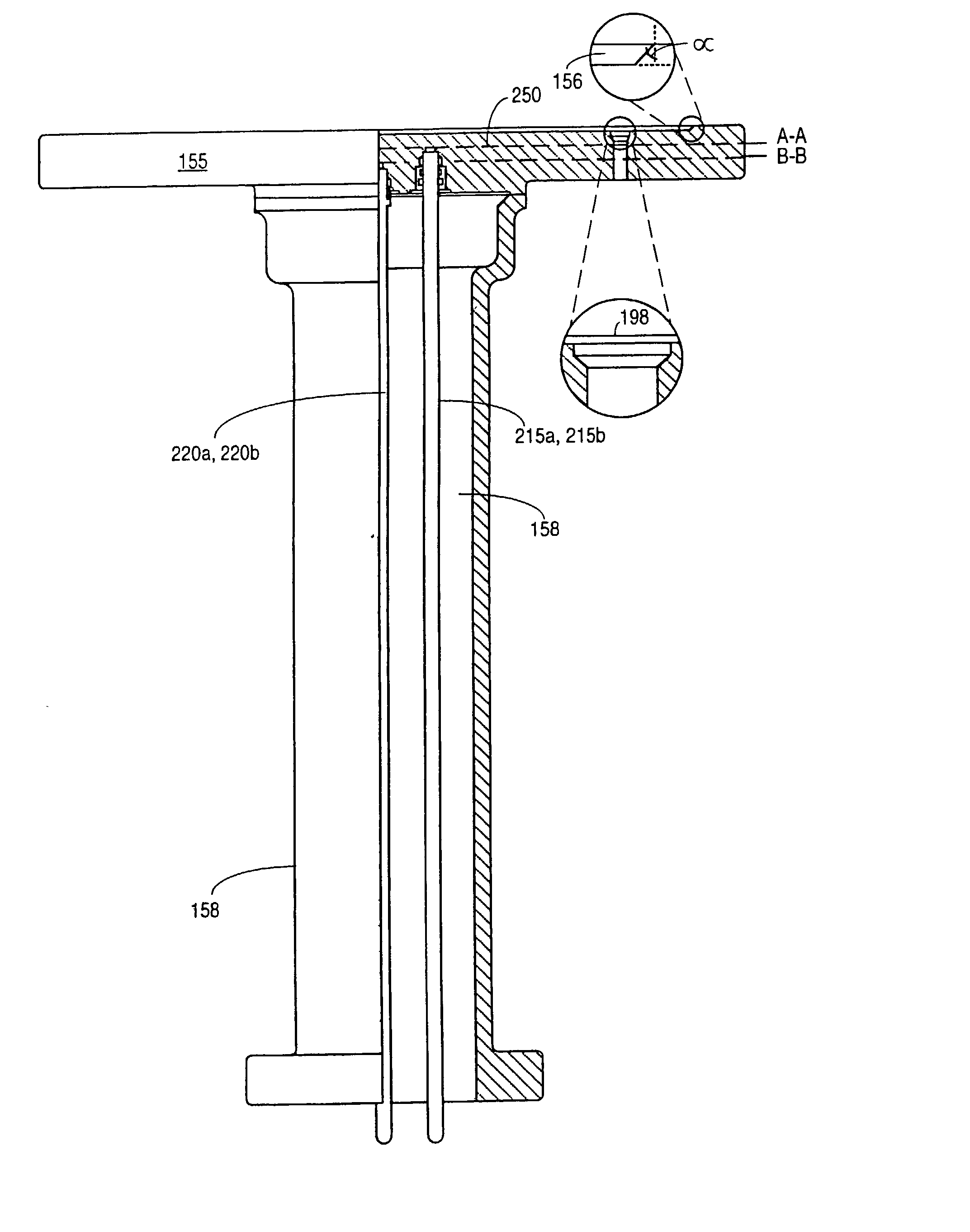
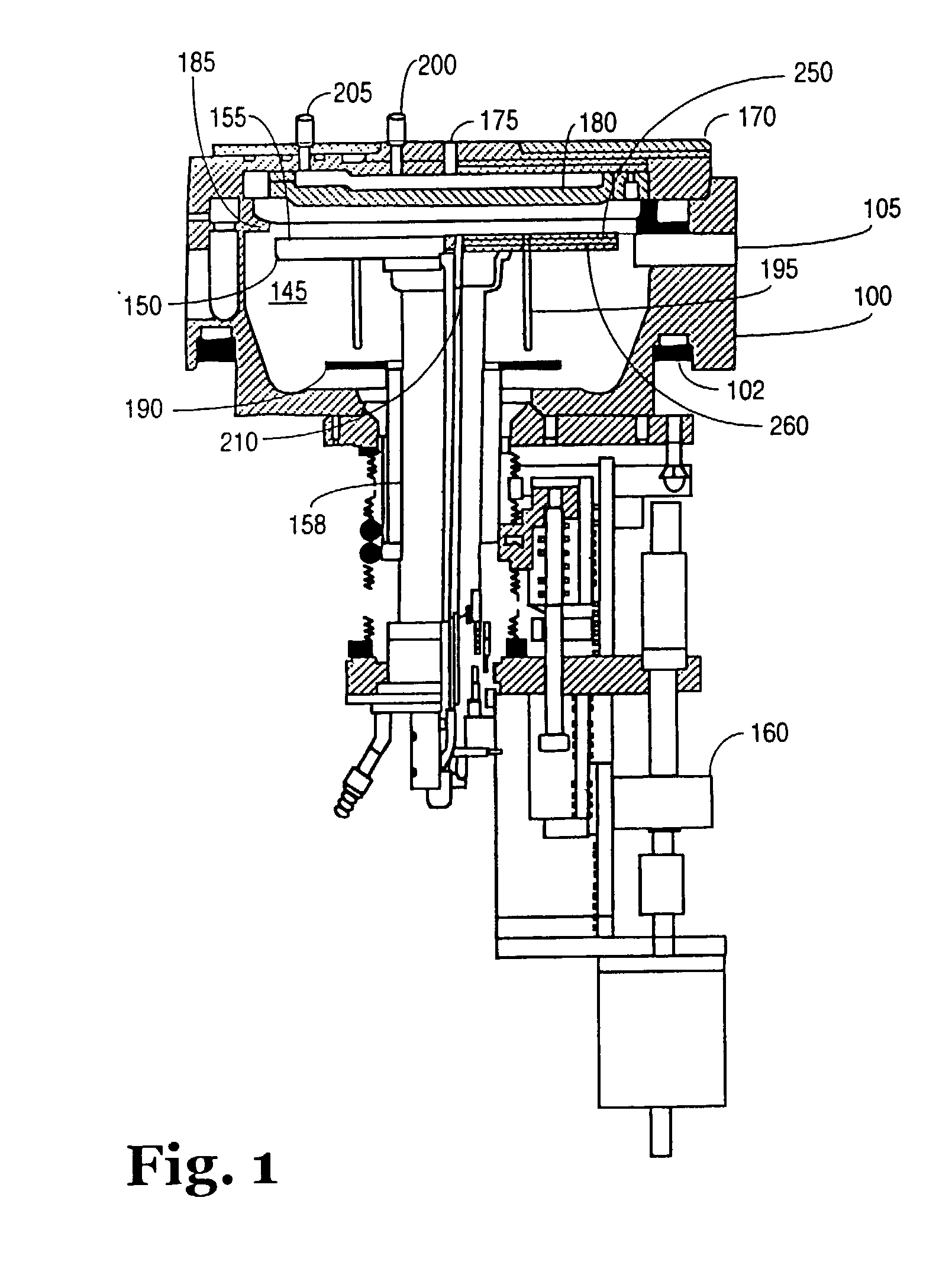
A heating apparatus including a stage comprising a surface having an area to support a wafer and a body, a shaft coupled to the stage, and a first and a second heating element. The first heating element is disposed within a first plane of the body of the stage. The second heating element is disposed within a second plane of the body of the stage at a greater distance from the surface of the stage than the first heating element, and the second heating element is offset from the first heating element in a plane substantially parallel to at least one of the first plane and the second plane.

Description

[0001] This application is a Continuation-In-Part of co-pending U.S. Application Serial No. 10 / 037,151 filed on Oct. 19, 2001, which is a Divisional Application of U.S. Pat. No. 6,423,949 issued on Jul. 23, 2002.[0002] 1. Field[0003] Heating mechanisms for process chambers, particularly, heating mechanisms for chemical vapor deposition chambers.[0004] 2. Description of Related Art[0005] Chemical vapor deposition (CVD) is a popular process for depositing various types of films on substrates and is used extensively in the manufacture of semiconductor-based integrated circuits such as, for example, the processing of semiconductor wafers to form individual integrated circuit device. In typical CVD processing, a wafer or wafers are placed in a deposition or reaction chamber and reactant gases are introduced into the chamber and are decomposed and reacted at a heated surface to form a thin film on the wafer or wafers.[0006] In general, there are single-wafer and multi-wafer CVD reaction c...

Claims


Application Information

Patent Timeline
IPC IPC(8): H01L21/00
CPCH01L21/67103H01L21/67248H01L21/67109H01L21/68792
Inventor HO, HENRYCUI, ANQINGYUAN, XIAOXIONG
Owner APPLIED MATERIALS INC
Learn More