Multi-threshold flip-flop circuit having an outside feedback

a flip-flop circuit and multi-threshold technology, applied in the field of flip-flop circuits and multi-threshold flip-flop circuits having an outside feedback, can solve the problems of circuits having significant increased complexity, low threshold voltage giving rise to a higher sub-threshold leakage current, and increasing the relative level of leakage currents

Inactive Publication Date: 2003-04-10
IBM CORP
View PDF0 Cites 38 Cited by
  • Summary
  • Abstract
  • Description
  • Claims
  • Application Information

AI Technical Summary

Problems solved by technology

However, a lower threshold voltage will give rise to a higher subthreshold leakage current.
Especially for battery-powered electronic devices, the relative level of leakage currents increases even more during sleep mode.
Such switching scheme works well for combinational circuits but not for sequential circuits because a latch or flip-flop circuit will lose its logical state when the supply voltage is turned off.
However, all the prior art solutions typically result in circuits having significant increased complexity with a large chip area overhead.
In addition, most prior art solutions have non-trivial issues related to saving and restoring state.

Method used


Image

  • Multi-threshold flip-flop circuit having an outside feedback
  • Multi-threshold flip-flop circuit having an outside feedback
  • Multi-threshold flip-flop circuit having an outside feedback

Examples


Embodiment Construction

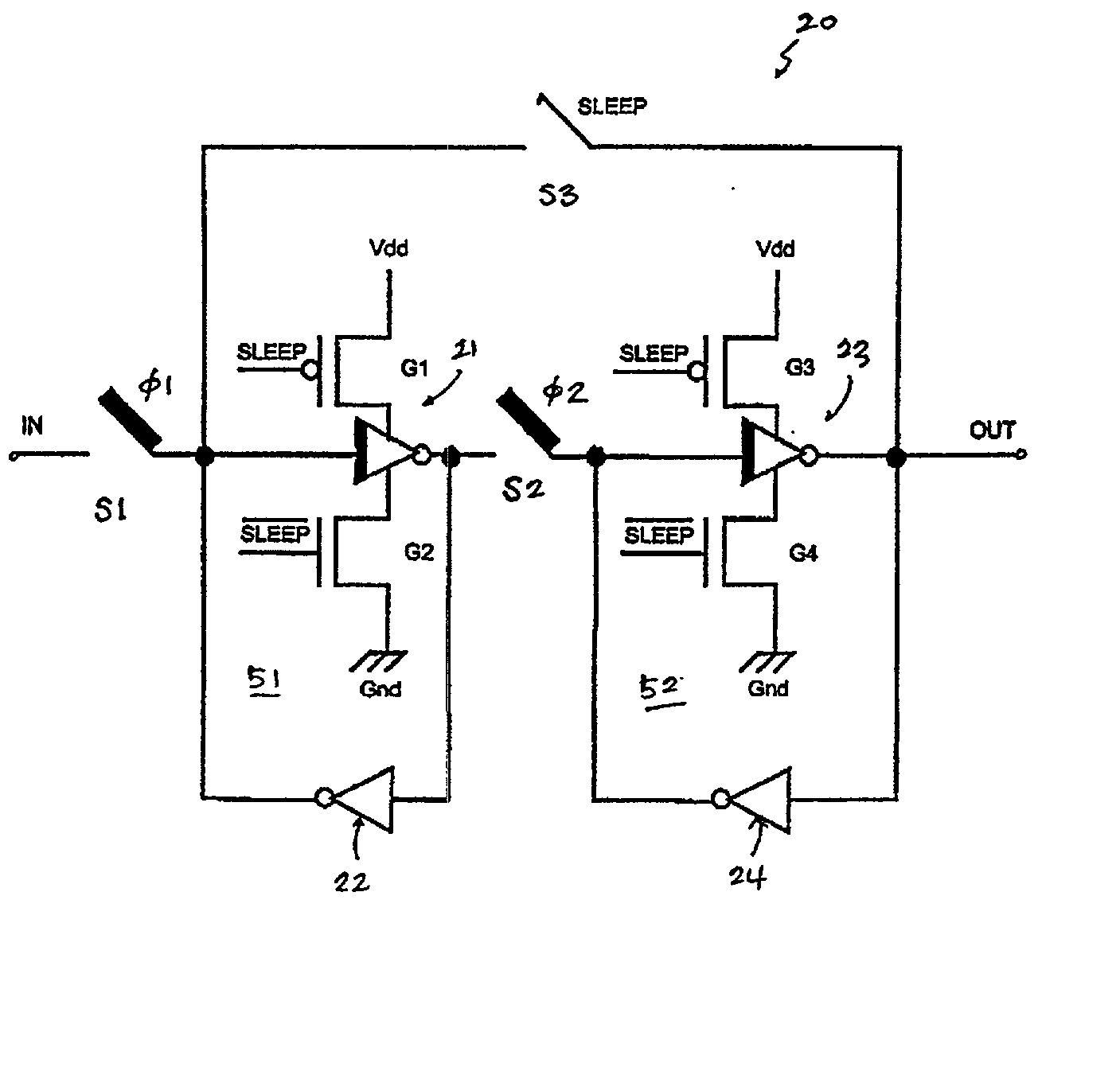
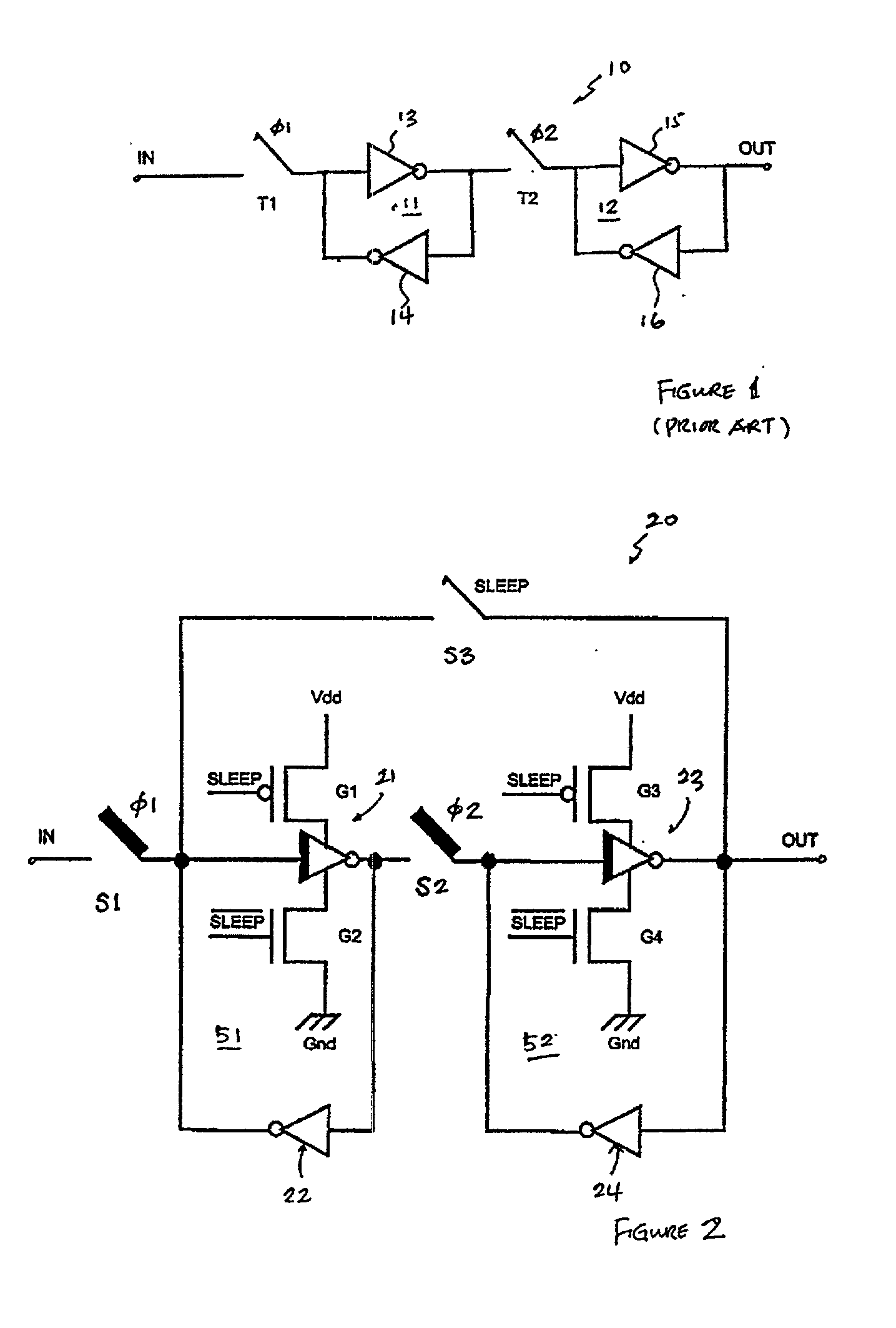
[0014] Referring now to the drawings and in particular to FIG. 1, there is depicted a circuit diagram of a typical master-slave flip-flop circuit, according to the prior art. As shown, a flip-flop circuit 10 includes a master latch 11 and a slave latch 12. Flip-flop circuit 10 has two clock phases, namely, {umlaut over (l)}.dagger.1 and {umlaut over (l)}.dagger.2. Switches S1 and S2, which can be pass gates or pass transistors, are activated by clock phases {umlaut over (l)}.dagger.1 and {umlaut over (l)}.dagger.2, respectively. By convention, a switch is closed when the clock is at a logical high (i.e., a logical one), and the switch is opened when the clock is at a logical low (i.e., a logical zero). For flip-flop circuit 10 to function correctly, clock phases {umlaut over (l)}.dagger.1 and {umlaut over (l)}.dagger.2 need to be non-overlapping (i.e., off-phase with each other). When clock phase {umlaut over (l)}.dagger.1 is high, master latch 11 is transparent and slave latch 12 i...


PUM


Abstract

A multi-threshold flip-flop circuit having an outside feedback is disclosed. The multi-threshold flip-flop circuit comprises a master latch and a slave latch. Coupled between an output of the slave latch and an input of the master latch, a switchable feedback path is utilized to retain logical values of the slave latch during a sleep mode of the flip-flop circuit.

Description

[0001] 1. Technical Field[0002] The present invention relates to logic circuits in general, and in particular to flip-flop circuits. Still more particularly, the present invention relates to a multi-threshold flip-flop circuit having an outside feedback.[0003] 2. Description of the Prior Art[0004] In order to maintain high performances in electronic devices having a scaled-down power supply voltage, threshold voltages for transistors within the electronic devices need to be scaled down also. However, a lower threshold voltage will give rise to a higher subthreshold leakage current. Especially for battery-powered electronic devices, the relative level of leakage currents increases even more during sleep mode. One solution for reducing the amount of current leakage in sleep mode is to use a circuit commonly known as multi-threshold complementary-metal-oxide semiconductor (MTCMOS) circuit. Generally speaking, a MTCMOS circuit uses low-threshold transistors during active mode but cuts o...

Claims


Application Information

Patent Timeline
Patent Type & Authority Applications(United States)
IPC IPC(8): H03K3/012H03K3/356H03K3/3562
CPCH03K3/012H03K3/35625H03K3/356008
Inventor STAN, MIRCEAJASMIN, JAMES E.
Owner IBM CORP
Why Eureka
Try Eureka