Multi-row rolling mills, methods of operating these mills, and rolling equipment using the mills

a multi-row rolling mill and mill technology, applied in the direction of flexible work arrangements, counter-pressure devices, manufacturing tools, etc., can solve the problems of high product loss ratio, large scale of hot rolling equipment intended for mass production, uneven productivity,

Inactive Publication Date: 2003-04-17
HITACHI LTD
View PDF1 Cites 8 Cited by
  • Summary
  • Abstract
  • Description
  • Claims
  • Application Information

AI Technical Summary

Problems solved by technology

Such hot-rolling equipment intended for mass production is very large in scale.
For the recent types of tandem rolling mills, since hot coils are connected upstream by welding and then rolled continuously, their productivity is uneven because only the extremely narrow areas including the welded connections may not be rolled to the desired thickness.
The above-described twin-stand reversing mill, therefore, is extremely high in product loss ratio.
The twin-stand reversing mill, although better in production yield than the single-stand reversing mill, is not sufficient in production volume, since the former mill does not does not have such a stand-to-stand distance as provided in the latter mill.
Since the clearance between the roll groups of the twin-reversing mill is short, human access to the roll groups in the event of workpiece breakage or thinning-down trouble is difficult and operations from removing the workpiece from the roll groups to recovering the corresponding machine components become time-consuming jobs, with the result that the rolling equipment decreases in availability.

Method used


Image

  • Multi-row rolling mills, methods of operating these mills, and rolling equipment using the mills
  • Multi-row rolling mills, methods of operating these mills, and rolling equipment using the mills
  • Multi-row rolling mills, methods of operating these mills, and rolling equipment using the mills

Examples


embodiment 1

[0045] (Embodiment 1)

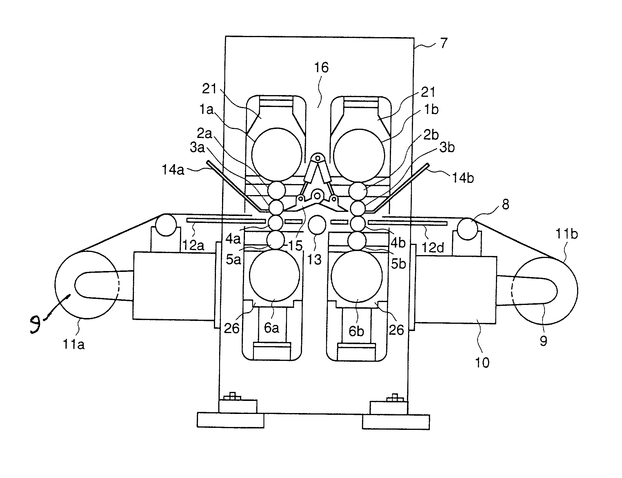
[0046] An embodiment of the present invention is described below using drawings. FIG. 1 is a front view of a multi-stage rolling mill constructed according to a first embodiment of the invention.

[0047] The multi-stage rolling mill shown in FIG. 1 has two roll groups, "a" and "b". The first roll group comprises an upper reinforced roll 1a, an upper middle roll 2a, an upper work roll 3a, a lower work roll 4a, a lower middle roll 5a, and a lower reinforced roll 6a. The second roll group comprises an upper reinforced roll 1b, an upper middle roll 2b, an upper work roll 3b, a lower work roll 4b, a lower middle roll 5b, and a lower reinforced roll 6b. The arrangement with these two roll groups consisting of six stages is taken as an example in the following description of the first embodiment.

[0048] The two roll groups in this rolling mill are contained and accommodated in a housing 7. A deflector roller 8, a tension reel 9, and a frame 10 for supporting the deflector...

embodiment 2

[0070] (Embodiment 2)

[0071] FIG. 4 is a plan view showing another embodiment of the present invention. The equipment in this embodiment comprises motors 38a and 38b for rotationally driving rolls, reduction gears 39a and 39b for obtaining a suitable rotational speed, and spindles 40a and 40b for transmitting a torque to the rolls. These components drive the rolls rotationally for workpiece rolling operations.

[0072] Both tension reels 9a and 9b have a driving motor 41a or 41b and a driving spindle 42a or 42b, and these components give suitable tension to workpiece 11 for its rotational driving.

[0073] In the equipment, a roll changing unit for rapidly changing the respective rolls of two roll groups is provided at the operating side of the rolling mill, namely, the opposite side of its driving means.

[0074] For this roll changing unit, a coil placement table 43a or 43b for workpiece 11 is provided at both sides of the rolling direction, at the operating side of the rolling mill. For th...

embodiment 3

[0082] (Embodiment 3)

[0083] FIG. 8 is a view of a conventional tandem rolling mill. Similarly, FIG. 9 is a view showing an example in which a multi-row rolling mill based on the present invention is applied to a tandem rolling mill, and FIG. 10 is a view showing another example in which a multi-row rolling mill based on the present invention is applied to a tandem rolling mill. For the purpose of comparison with a conventional four-stand tandem rolling mill, the overall lengths of the three types of equipment are shown as L1, L2, and L3, in the figures. The stand-to-stand distance in FIG. 8 is 5 m, whereas that of the multi-row rolling mill is 1.8 m. Hence, the equipment in the case of L2 can be reduced to a length 3.2 m shorter than in the case of L1, and L3 is 6.4 m shorter, which indicates that the equipment can be reduced by 42.7% in length.

[0084] Although all the above-described embodiments of the present invention apply to the case that the rolling mill has six stages of roll ...


PUM

PropertyMeasurementUnit
thicknessaaaaaaaaaa
thicknessaaaaaaaaaa
lengthaaaaaaaaaa

Abstract

A multi-row rolling mill has in one housing at least two groups of rolls including at least one pair of work rolls, and constructed so that when the workpiece to be rolled is passed one time, it can be rolled using said respective work rolls. The multi-row rolling mill is characterized in that it is provided with a means for removing the workpiece if the workpiece stops moving between said roll groups.

Description

BACKGROUND OF INVENTION[0001] This application claims the priority of Japanese Application No. 2001-314967, filed in Japan on Oct. 12, 2001, the disclosure of which is expressly incorporated by reference herein.[0002] 1. Field of the Invention[0003] The present invention relates to multi-row rolling mills, methods of operating these mills, and rolling equipment that uses the mills.[0004] 2. Description of Prior Art[0005] Hot coils, the materials to be cold-rolled, are produced using hot-rolling equipment. Under prior art, slabs 200 mm or more in thickness are cast by a continuous casting machine and these slabs are then provided with unidirectional or reversing-type rolling by a plurality of pre-rolling mills to form bar materials. After these bar materials have been further rolled to the required thickness by a tandem rolling mill group consisting of a plurality of continuously arranged rolling mills, the bar materials are cooled by a cooling apparatus and wound by a coiler to form...

Claims


Application Information

Patent Timeline
Patent Type & Authority Applications(United States)
IPC IPC(8): B21B1/22B21B1/24B21B1/26B21B1/32B21B13/02B21B13/14B21B29/00B21B31/02B21B31/10B21B31/22B21B31/30B21B33/00B21B39/16
CPCB21B1/24B21B1/32B21B29/00B21B31/02B21B31/103B21B31/106B21B2269/06B21B31/30B21B33/00B21B39/16B21B2013/021B21B2013/028B21B2269/04B21B31/22
Inventor HORII, KENJIGOTO, AKIRAKOBAYASHI, HIDEOKASAI, SYUNSAKUKOBAYASHI, YUJIROSAKANAKA, TAKAOFUJII, MOTOYUKI
Owner HITACHI LTD
Why Eureka
Try Eureka