Device for charging a bulk material into a container and method for the use thereof

a technology for charging devices and bulk materials, applied in the field of devices, can solve problems such as inability to precisely determine the net filling quantity, inability to prevent at least some dust from escaping into the surroundings, and inability to use connecting forces

Inactive Publication Date: 2003-04-24
GLATT SYSTTECHN +1
View PDF3 Cites 8 Cited by
  • Summary
  • Abstract
  • Description
  • Claims
  • Application Information

AI Technical Summary

Problems solved by technology

The disadvantage here is that it is not possible to prevent at least some dust from escaping into the surroundings, or relatively high-outlay sealing of the hopper mouth and of the dust-return line in relation to the opening of the container which is to be loaded is necessary

Method used


Image

  • Device for charging a bulk material into a container and method for the use thereof
  • Device for charging a bulk material into a container and method for the use thereof
  • Device for charging a bulk material into a container and method for the use thereof

Examples


exemplary embodiment i

[0024] Exemplary Embodiment I

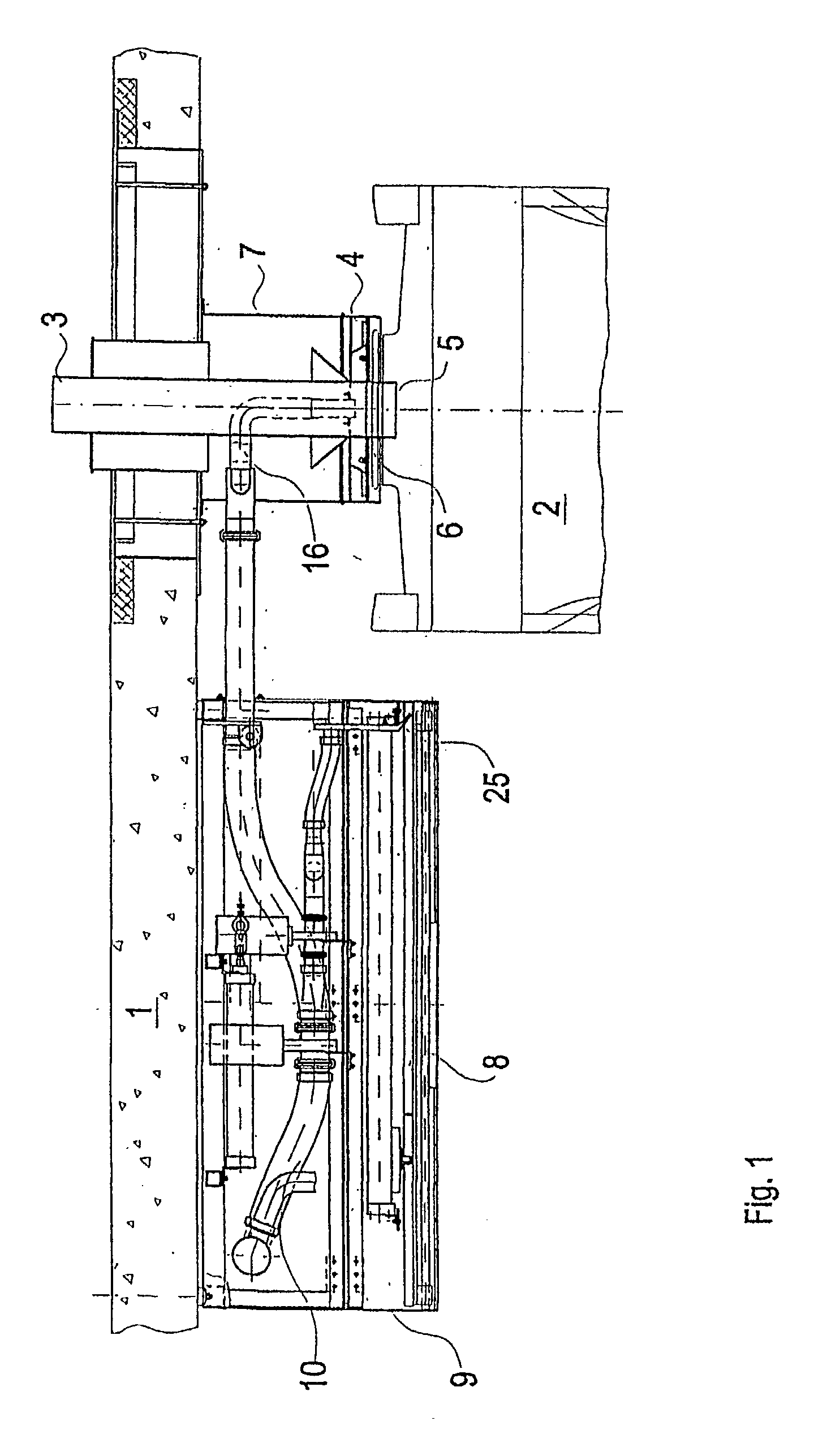
[0025] FIG. 1 shows, in respect of exemplary embodiment I, an apparatus according to the invention which is arranged on a ceiling 1. Non-illustrated silos or installations for producing a pharmaceutical powder as the bulk goods may be located above the ceiling. This powder is intended to be transferred into the container 2 beneath the ceiling 1. In this case, the container 2 is mounted on weighing scales, which are intended to determine the precise net filling quantity of powder.

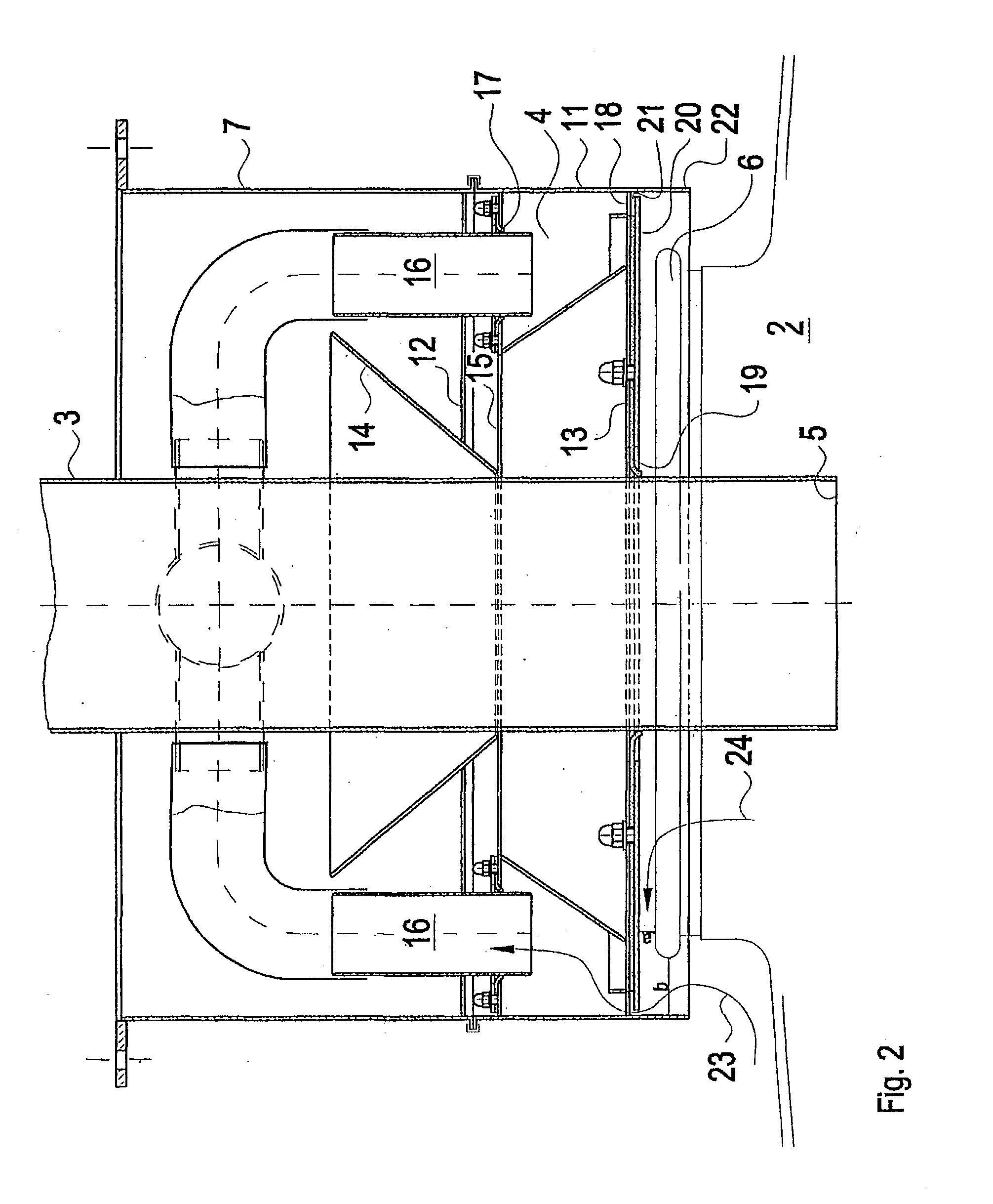
[0026] The actual apparatus according to the invention comprises a closed housing 4 with air-intake tubes 16 and an annular gap 21. Leading through the housing 4 is a filling tube 3, of which the outlet opening 5 penetrates into the introduction opening 6 of the container 2.

[0027] The housing 4 is secured on the ceiling 1 via a load-bearing apparatus 7. A slide 8 is arranged, as protecting means, to the side of the housing 4 and of the outlet opening 5. In the rest position, when...

exemplary embodiment ii

[0041] Exemplary Embodiment II

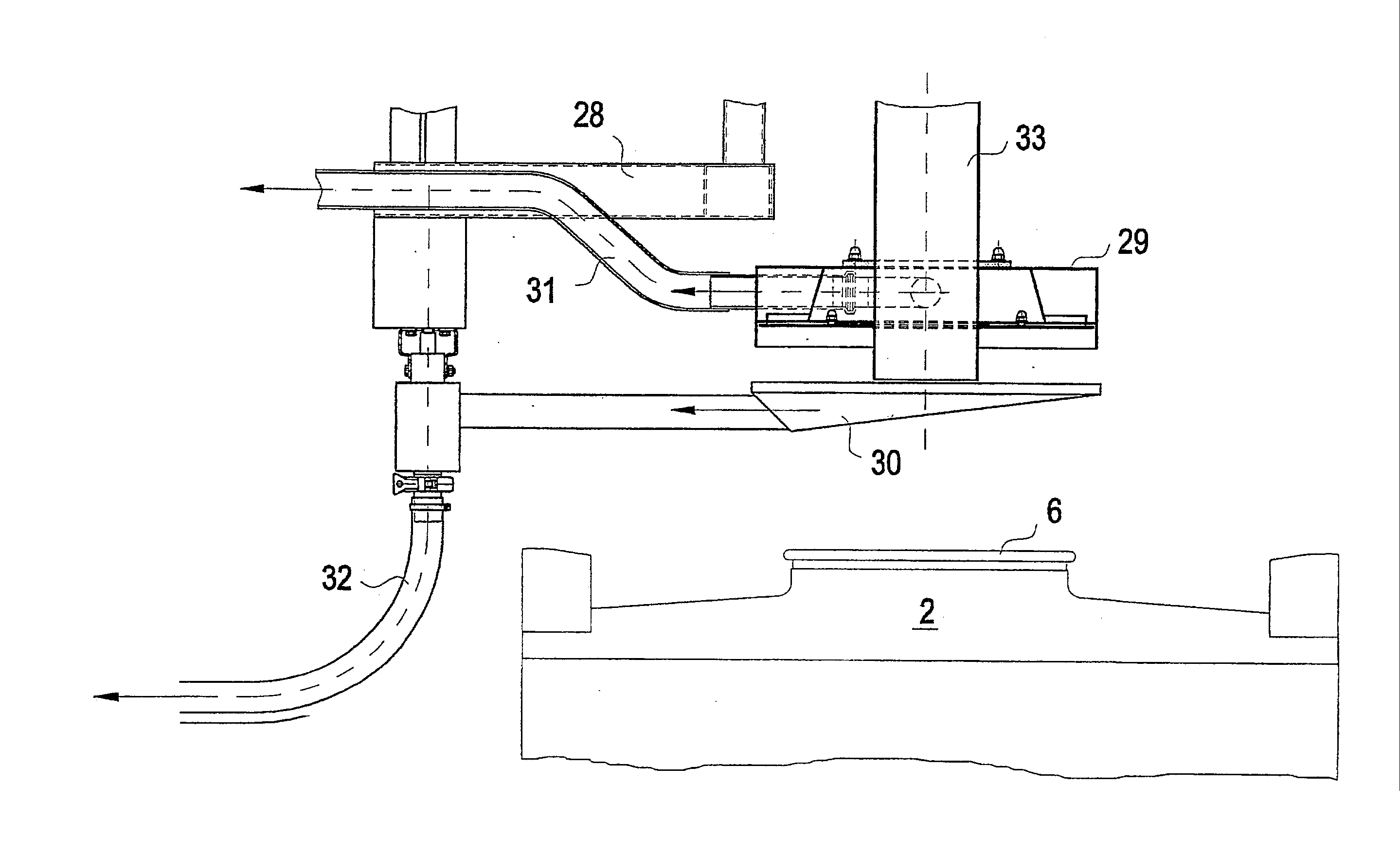
[0042] FIG. 3 illustrates a floor-supporting apparatus according to the invention. The support 28 is only indicated in part. Its actual form is adapted to the conditions. Secured on the support 28 are a housing 29, a protecting means, in the form of a pivoting plate 30, and pipelines 31 and 32, which lead to an arrangement for extracting dust by suction. A filling tube 33 is routed through the housing 29. The specific design of the housing 29 is largely similar to the housing 4 in exemplary embodiment I.

[0043] In FIG. 3, a container 2 with an introduction opening 6 is located in a lowered position in relation to the housing 29, and the protecting means 30 is located beneath the housing 29 and the filling tube 33. In this case, in exemplary embodiment II, the entire plate-like protecting means 30 is connected, via the pipeline 32, to the arrangement for extracting dust by suction, and residues of bulk goods dropping out of the filling tube 33 or of the h...


PUM


Abstract

The apparatus has a closed housing (4, 29), one side of the housing (4, 29) being the filling side (13), which, during filling of the container (2), is located opposite an introduction opening (6) provided in said container. The housing (4) has a filling tube (3, 33) passing through it axially in relation to the axis of the introduction opening (6), said filling tube, on the filling side (13), protruding to such an extent that, in the filling position, projects into the introduction opening (6). The interior of the housing (4, 29) is connected to an external arrangement for extracting dust by suction, and the filling side (13) has an air-inlet opening. In respect of the process, for the purpose of filling the container (2), the filling side (13) of the housing (4) is positioned above the introduction opening (6) of the container (2) such that a gap (a) is produced between the filling side (13) and the introduction opening (6), and the arrangement for extracting dust by suction is set in operation at least during filling of the container (2).

Description

[0001] The invention relates to an apparatus for introducing bulk goods into a container, the apparatus having an arrangement for extracting dust, which can pass into the surroundings during filling of the container, by suction. The invention also relates to a process for using an apparatus according to the invention.PRIOR ART[0002] Various apparatuses for introducing bulk goods into containers are known from the prior art. Relevant apparatuses in the present case are those which are suitable for dust-containing bulk goods or for bulk goods in which dust may be produced, for example, by abrasion during transfer.[0003] Open ventilator cowls, which are arranged above the filling location, are known in general.[0004] DE 42 11 855 A1 describes an arrangement for loading bulk goods. In one embodiment, a dust-removal nozzle is provided in the region where the bulk goods enter the loading arrangement. A dust-return line results in dust-laden air being returned from the container which is t...

Claims


Application Information

Patent Timeline
IPC IPC(8): B65G69/18B65G65/32
CPCB65G69/182
Inventor DOERFFEL, WOLFGANGKRIEGER, SIEGFRIED
Owner GLATT SYSTTECHN
Why Eureka
Try Eureka