Turbomolecular pump

a technology of molecular pump and collision rate, which is applied in the direction of non-positive displacement pumps, liquid fuel engines, mechanical equipment, etc., can solve the problems of small collision rate of molecules, small losses, and small overall dimensions of pumps, so as to reduce heat generation, reduce power consumption, and reduce the collision rate of molecules.

Active Publication Date: 2005-09-22
PFEIFFER VACUUM GMBH
View PDF8 Cites 4 Cited by
  • Summary
  • Abstract
  • Description
  • Claims
  • Application Information

AI Technical Summary

Benefits of technology

[0013] The more shallow blade angle has a number of positive results: firstly, at the same overlap ratio, the number of blades per disc is smaller despite a small disc height. In addition, swirling in the high pressure region is prevented which results in reduction of power consumption and in reduction of heat generation. Small disc and blade heights result in a smaller collision rate of the molecules and, thereby, in smaller losses. Finally, the small disc and blade heights result in smaller overall dimensions of the pump. The reduction in the number of indentation leads to a further reduction of compression power. Moreover, a robust construction of pump stages, resistant to dust and corrosive gases, becomes possible, which favorably influences the compression forces. The smaller is the number of blades, the smaller are axial compression forces that act on the blades and, thus, less energy is required for driving the turbomolecular pump. Overall, the present invention results in a compact construction, in improved power characteristics of the outlet stages and, thereby, of the entire pump.

Problems solved by technology

Small disc and blade heights result in a smaller collision rate of the molecules and, thereby, in smaller losses.
Finally, the small disc and blade heights result in smaller overall dimensions of the pump.

Method used


Image

  • Turbomolecular pump
  • Turbomolecular pump

Examples


Embodiment Construction

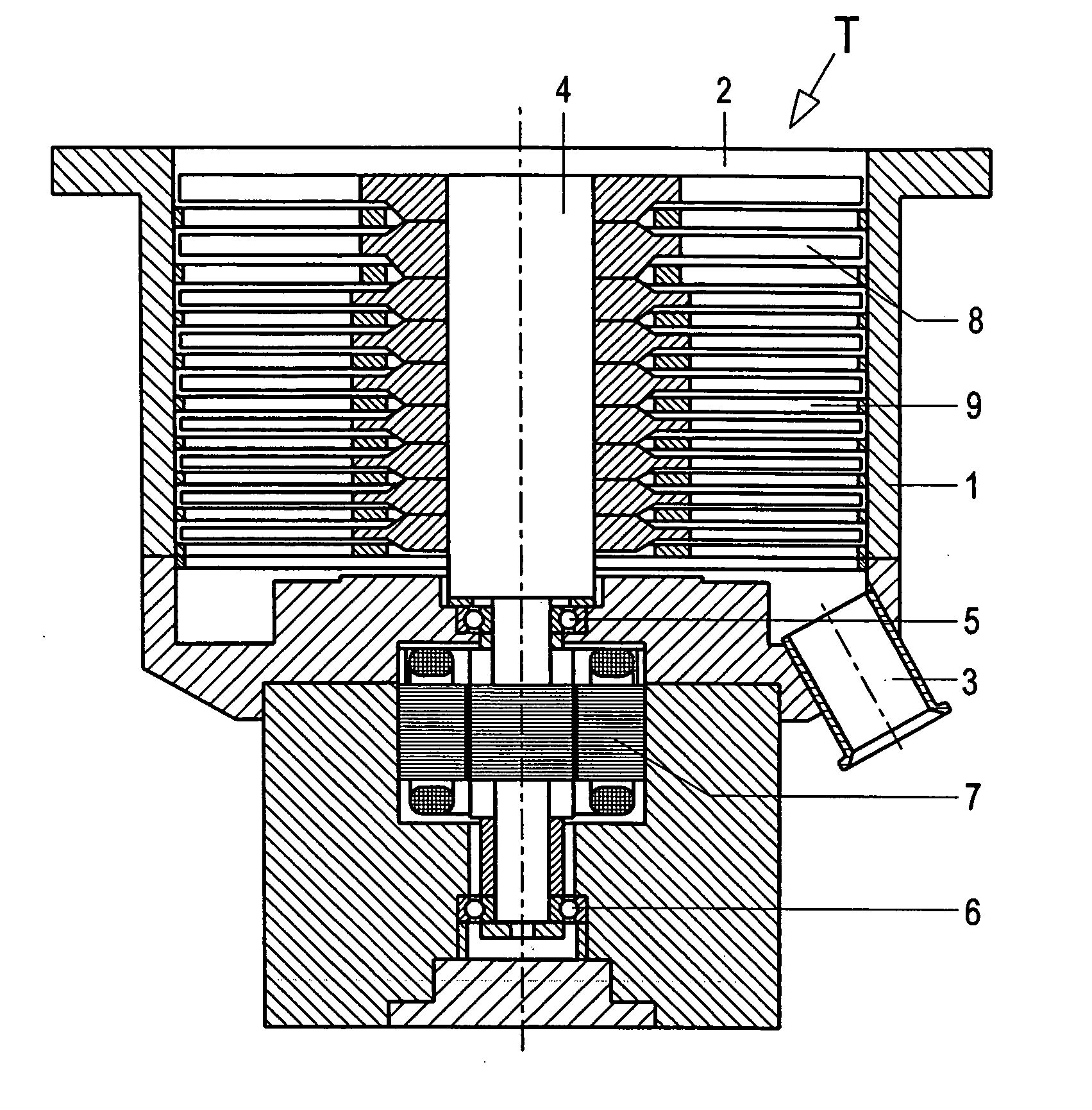
[0025] A turbomolecular pump T according to the present invention, which is shown in FIG. 1, has a housing 1 at one end of which there is provided a suction flange 2 formed integrally with the housing, and at the other end of which, there is provided an outlet flange 3. A rotor shaft 4 is arranged in the housing 1 and is rotatably supported in roller bearings 5 and 6. An electric motor drive 7 drives the rotor shaft 4 with a high rotational speed. A plurality of rotor discs 8 are fixedly secured on the rotor shaft 4. The rotor discs 8 cooperate with stator disc 9 provided in the housing 1.

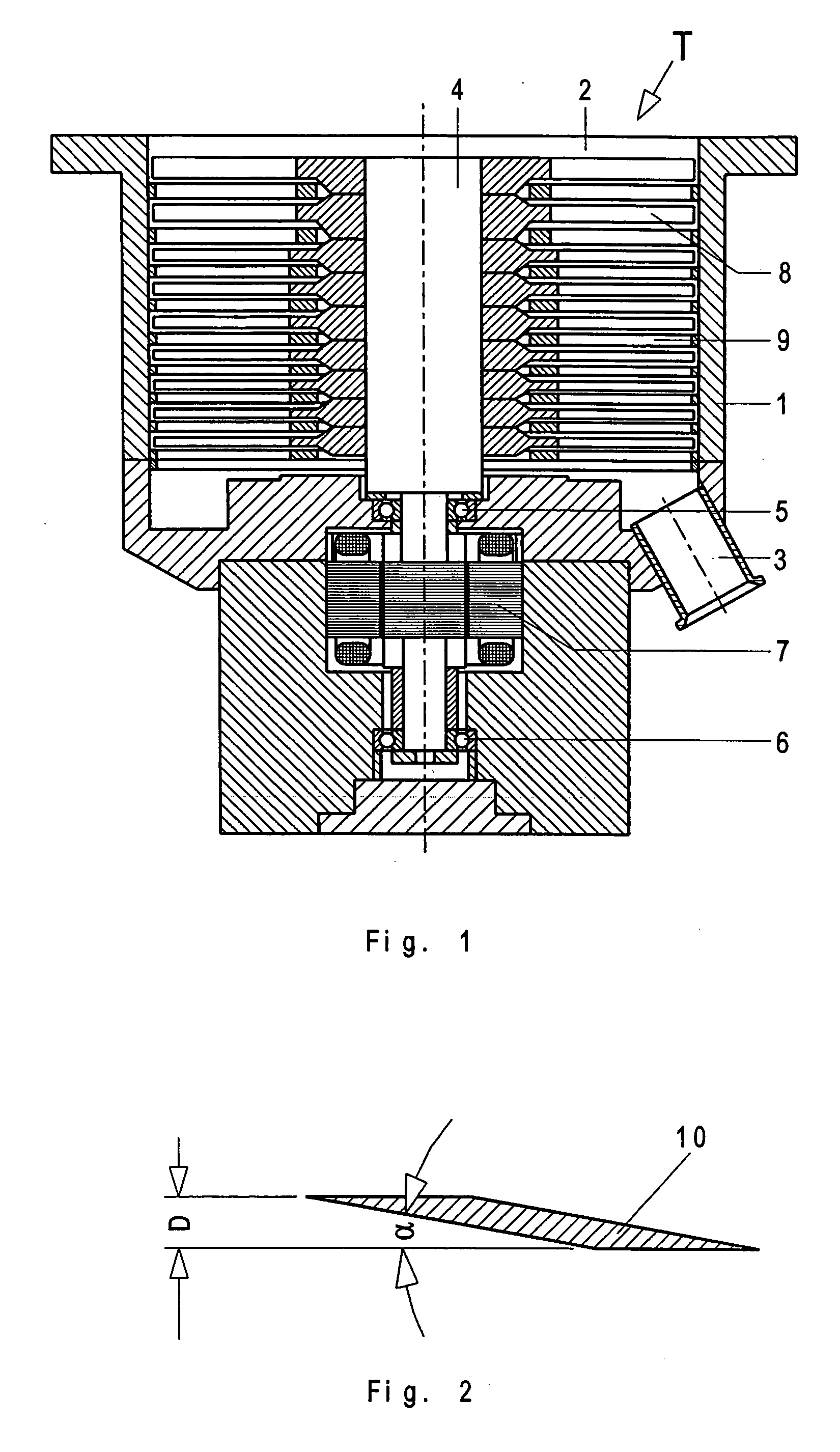
[0026] The groups of rotor discs 8 and stator discs 9, which are located adjacent to the pump outlet and to the outlet flange 3 have blades 10 with a blade angle between 4.6° and 5.9°. The blade angle α is shown in FIG. 2 at a substantially increased scale. The discs 8, 9 have a thickness that a amounts to form about 3 mm to about 4.5 mm.

[0027] The blades 10 have a cross-section that at least som...


PUM


Abstract

A turbomolecular pump includes a plurality of alternatively axially arranged one behind another, rotor and stator discs (8,9) provided with blades (10), with the blades (10) located in vicinity of the high vacuum side (2) having a blade angle (α) that is steeper than blade angle (α) of the blades (10) located in vicinity of the vacuum side (3), and with the blade angle (α) of the blades (10) located in the vicinity of the vacuum side (3) amounting to less than 8°.

Description

BACKGROUND OF THE INVENTION [0001] 1. Field of the Invention [0002] The present invention relates to a turbomolecular pump including a plurality of alternatively axially arranged one behind another, rotor and stator discs provided with blades, with the blades located in vicinity of the high-vacuum side having a blade angle that is steeper than a blade angle of the blades located in the vicinity of the vacuum side. The present invention also relates to a method of manufacturing of rotor and stator discs provided with blades having such blade angles for the turbomolecular pump. [0003] 2. Description of the Prior Art [0004] Turbomolecular pumps of the type described above are well known. E.g., such turbomolecular pumps are disclosed in German Publications DE 2 035 063 B3 and DE 27 17 366 B2. The blades of these pumps have a cross-section of a parallelogram. The blade angle amounts to, dependent on an axial position of the blade, from 25° to 40°. [0005] German Publication DE 101 03 230 ...

Claims


Application Information

Patent Timeline
Patent Type & Authority Applications(United States)
IPC IPC(8): F04D19/04
CPCF04D19/042F04D29/544F04D29/324F05D2250/70
Inventor CONRAD, ARMINFAHRENBACH, PETER
Owner PFEIFFER VACUUM GMBH
Why Eureka
Try Eureka