
Energy-absorbing flexible polymer vehicle wheel

a flexible, energy-absorbing technology, applied in the direction of vehicle components, non-metallic wheel bodies, rolling resistance optimization, etc., can solve the problems of metal wheels suffering from a number of disadvantages and limitations, general weight increase, lack of energy-absorbing flexibility

Inactive Publication Date: 2003-05-01
HIPER TECH
View PDF0 Cites 37 Cited by
  • Summary
  • Abstract
  • Description
  • Claims
  • Application Information

AI Technical Summary

Benefits of technology

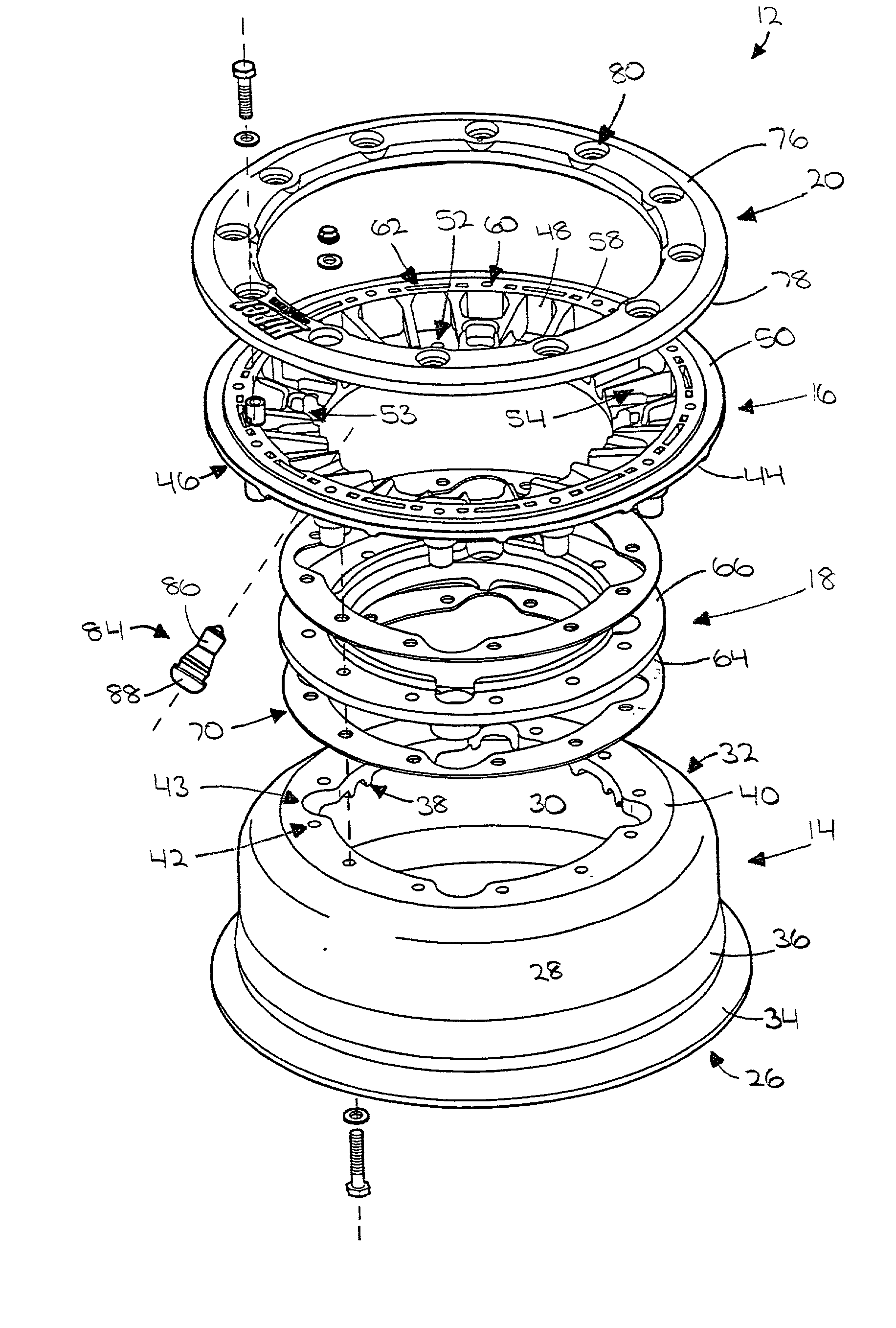
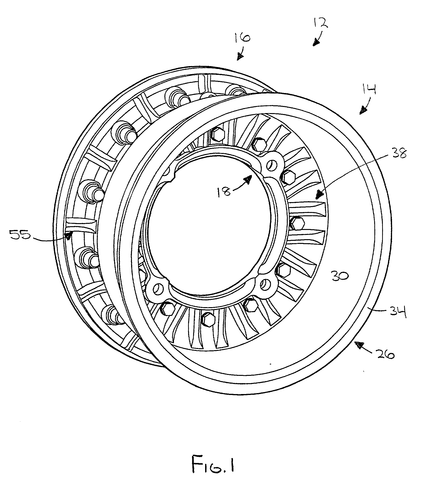
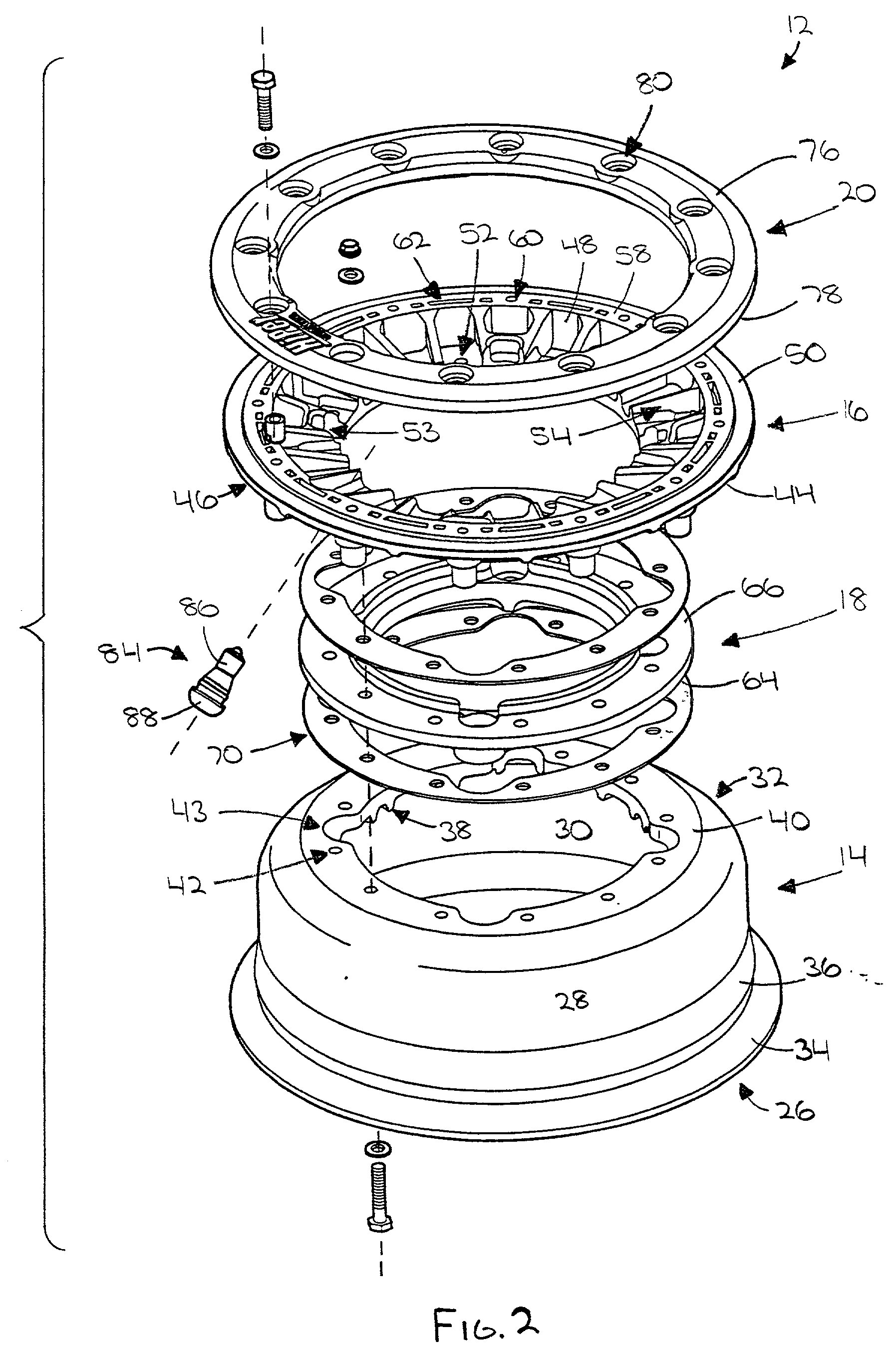
[0010] In a preferred first modular embodiment, the wheel broadly comprises an inboard wheel half; an outboard wheel half; a center section; a bead lock ring; and a mud plug. Preferably, at least the inboard wheel half and the outboard wheel half are constructed from the polymer. The inboard wheel half provides an inboard seal and support for the tire. The inboard wheel half presents an outwardly projecting bead flange or lip operable to contact and facilitate sealing thereagainst an inboard tire bead portion of the tire. The inboard wheel half also presents a circumferential tire locking rib in relatively close proximity to the bead flange and operable to facilitate retaining the tire on the wheel by restricting movement of the inboard tire bead.
[0014] The bead lock ring is operable, in cooperation with the bead lock surface of the outboard wheel half, to facilitate sealing the outboard tire bead by clamping it therebetween. The bead lock ring is a substantially circular ring of the polymer material, and presents a second portion of the aforementioned alignment mechanism in the form of a plurality of projections which interlockingly cooperate with the plurality of slots to facilitate proper alignment of the bead lock surface with the bead lock ring. The projections also function to advantageously transfer loads during impacts, thereby further avoiding damage to the wheel.
[0015] The mud plug is operable to substantially prevent mud and debris from entering an interior cavity or area of the outboard wheel half and becoming stuck or packed therewithin. The mud plug may be adapted for use on the inboard wheel half as well by providing a center opening and slit for accommodating an axle of the wheel. Thus, the mud plug feature prevents a build-up of mud which would otherwise add undesirable weight and potentially unbalance the wheel, thereby causing undesirable vibrations. Furthermore, the mud plug ensures quick and convenient access to a valve stem inlet and to a plurality of lug bolts and nuts coupling the wheel with the vehicle. The mud plug removably couples with the wheel using quick release quarter-turn fasteners.
[0016] It will be appreciated by those with skill in the relevant arts, that the present invention provides a number of advantages over the prior art, including the stiffening ribs and varying cross-sectional thicknesses which minimize weight while substantially increasing wheel stiffness to prevent cracking or fracture failure due to driving stresses. This stiffness, however, is balanced with maintaining equally desirable energy-absorbing flexibility. Furthermore, the O-rings, gaskets, or dynamic u-cup seals interposed between the center section and both the inboard wheel half and the outboard wheel half provide a highly advantageous seal therebetween. Additionally, the interlocking alignment mechanism of the bead locking surface and bead ring facilitates easier and more convenient tire mounting and sealing. Additionally, the easily and conveniently removable mud plug provides an advantageous mechanism for preventing interior areas of the inboard and outboard wheel halves from becoming packed with mud or debris, thereby preventing unwanted added weight and vibration while ensuring quick and easy access to the valve stem for inflating the tire and to the lug nuts or other mechanisms coupling the wheel to the vehicle.

Problems solved by technology

Unfortunately, metal wheels suffer from a number of disadvantages and limitations, including a generally heavier weight and a lack of energy-absorbing flexibility.
Aluminum, for example, though a relatively lightweight metal, when used in wheel construction must typically be made undesirably thick and correspondingly heavy to have the strength required to withstand the aforementioned punishing driving conditions.
Unfortunately, aluminum has a relatively low yield strength, meaning it is easily permanently deformed.
When such deformation occurs, tire leakage or de-beading may result.
Those with skill in the arts of off-road travel and off-road racing will appreciate these drawbacks and limitations and the expensive necessity of maintaining a supply of and frequently replacing aluminum wheels.
Steel, though stronger than aluminum, is also undesirably heavier and similarly subject to permanent deformation.
It will also be appreciated, from a manufacturing standpoint, that steel and aluminum may, at times, be difficult to acquire, and can be relatively difficult and dangerous to work.
Furthermore, delivery costs for the relatively heavy metal wheels can negatively impact profit margins.
Unfortunately, existing polymer wheels typically have little, if any, energy-absorbing flexibility.
Thus, rather than deform, as metal wheels are wont to do, they often crack or fracture under similar stresses, being therefore suitable only for use on very lightweight vehicles or very smooth, managed race courses.
Existing wheels, whether constructed from a metal or a polymer, suffer from a number of additional disadvantages as well, including bead rings that are difficult to align and install; center sections in modular wheels that are unsealed or poorly sealed; and interior cavities wherein mud and debris become packed due to lack of or unsophisticated mechanisms for preventing such a build-up which could add undesired weight, unbalance the wheel, and prevent or hinder access to the mechanisms, such as lug bolts and nuts, coupling the wheel to the vehicle.
Thus, the mud plug feature prevents a build-up of mud which would otherwise add undesirable weight and potentially unbalance the wheel, thereby causing undesirable vibrations.

Method used


Image

  • Energy-absorbing flexible polymer vehicle wheel
  • Energy-absorbing flexible polymer vehicle wheel
  • Energy-absorbing flexible polymer vehicle wheel

Examples


Embodiment Construction

, below.

[0018] A preferred embodiment of the present invention is described in detail below with reference to the attached drawing figures, wherein:

[0019] FIG. 1 is an isometric view of a preferred first modular embodiment of the present invention;

[0020] FIG. 2 is an exploded isometric view of the embodiment shown in FIG. 1;

[0021] FIG. 3 is an exploded isometric view of a center section component of the embodiment shown in FIG. 1;

[0022] FIG. 4 is a fragmented sectional elevation view of a dynamic u-cup seal component of the present invention;

[0023] FIG. 5 is an exploded fragmented perspective view of an outboard wheel half component and a bead ring component of the embodiment shown in FIG. 1;

[0024] FIG. 6 is a plan view of the embodiment shown in FIG. 1;

[0025] FIG. 7 is a sectional elevation view of the embodiment shown in FIG. 1 taken along line 1-1 of FIG. 6;

[0026] FIG. 8 is an exploded isometric view of a mud plug component and the bead ring component of the embodiment shown in F...


PUM


Abstract

A lightweight, energy-absorbing, flexible vehicle wheel (12) constructed from an injection molded engineered polymer, such as, for example, a toughened nylon reinforced with carbon fibers, glass fibers, or kevlar fibers, wherein the wheel (12) may be embodied in either modular or one-piece construction. In a modular embodiment, the wheel (12) comprises broadly comprises an inboard wheel half (14); an outboard wheel half (16); a center section (18); a bead lock ring (20); and a removable mud plug (22). Stiffening ribs (38,54,55) and varying cross-sectional thicknesses are provided in the inboard and outboard wheel halves (14,16) for controlling stiffness; gaskets (70), O-rings (71), or dynamic u-cup seals (73) are provided for sealing contact surfaces (40,44,64,66); and an interlocking alignment mechanism (62,82) is provided for aligning the bead ring (20) on the outboard wheel half (16).

Description

[0001] 1. Field of the Invention[0002] The present invention relates to wheels for vehicles. More particularly, the present invention relates to a lightweight, energy-absorbing, flexible vehicle wheel constructed from an injection molded engineered polymer, such as, for example, a toughened nylon reinforced with carbon fibers, glass fibers, or kevlar fibers, wherein the wheel may be embodied in either modular or one-piece construction, and comprises ribs and varying cross-sectional thicknesses for controlling stiffness; O-rings, gaskets, or dynamic u-cup seals for sealing contact surfaces; an alignment mechanism for facilitating bead ring alignment; and a mud plug having a quick release mechanism for quick removal.[0003] 2. Description of the Prior Art[0004] It is often desirable to provide a vehicle with lightweight wheels able to withstand substantial and repeated impacts and other operating stresses without significant negative effect or performance degradation. This is true for ...

Claims


Application Information

Patent Timeline
Patent Type & Authority Applications(United States)
IPC IPC(8): B60B5/02B60B25/00
CPCB60B5/02B60B23/10B60B25/002B60B2900/5116B60B25/08B60B25/20B60B25/22B60B25/008Y02T10/86
Inventor DARNELL, THOMAS A.
Owner HIPER TECH
Learn More