Apparatus and method for shunting induced currents in an electrical lead
an electrical lead and shunting technology, applied in the direction of internal electrodes, transvascular endocardial electrodes, therapy, etc., can solve the problems of discouraged use of implantable medical devices, vastly more sophisticated and complex, and capable of performing significantly more complex tasks
- Summary
- Abstract
- Description
- Claims
- Application Information
AI Technical Summary
Problems solved by technology
Method used
Image

Examples
first embodiment
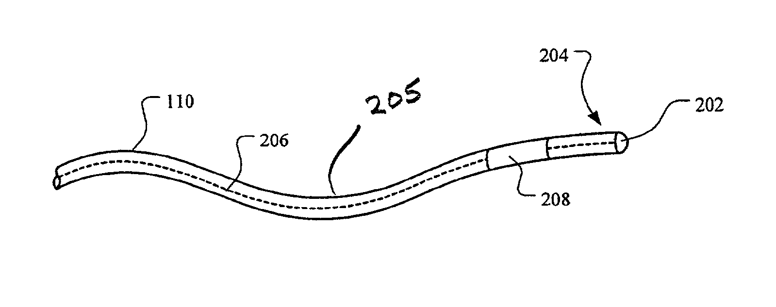
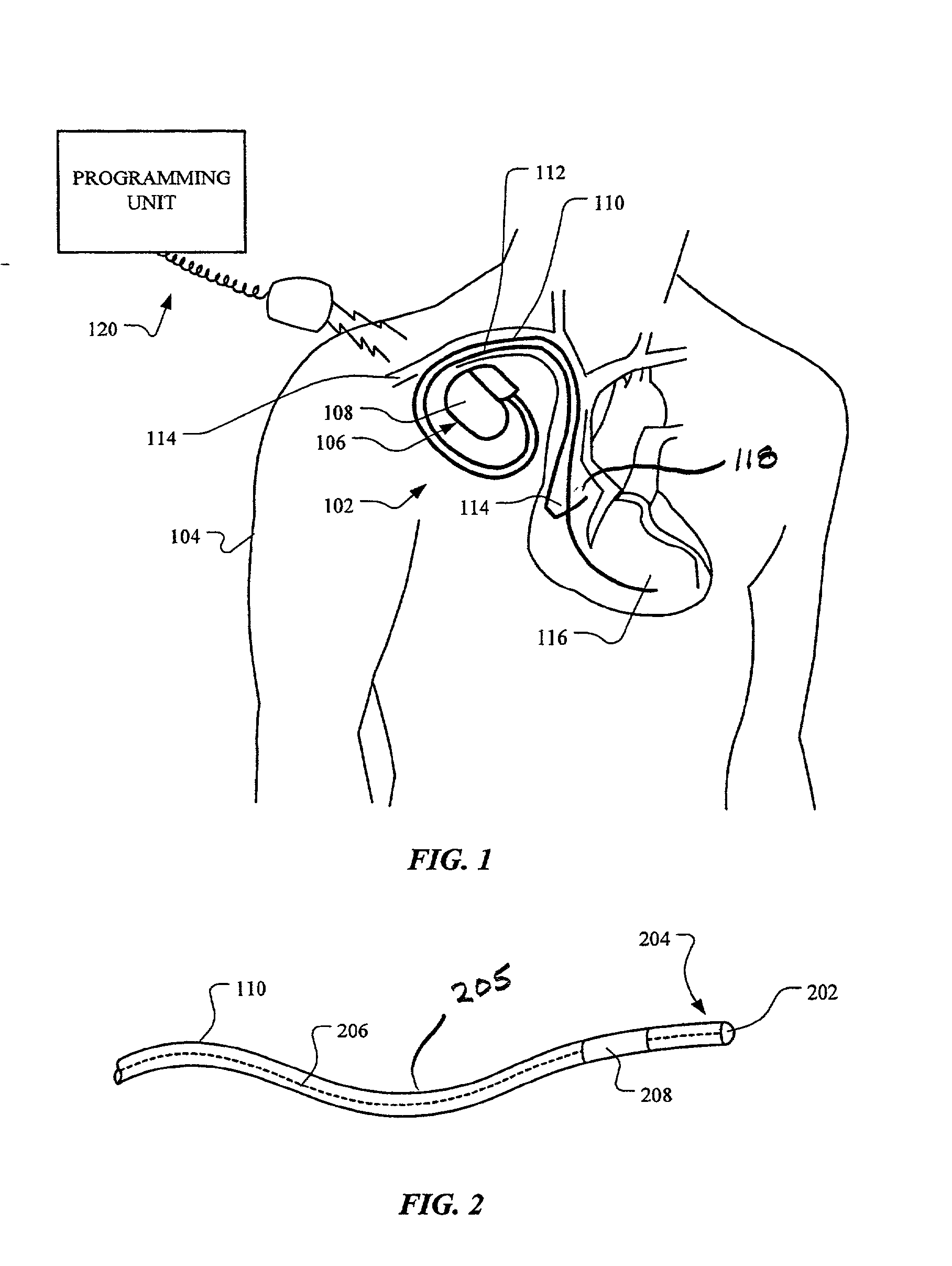
[0026] In a first embodiment, the implantable medical device 102 is a unipolar device in which the tip electrode 202 may serve as a cathode and the canister 108 may serve as an anode for pacing, stimulation, or sensing circuitry (not shown) of the implantable medical device 102. In this embodiment, as illustrated in FIGS. 2 and 3, a shunting assembly 208 includes a ring electrode 302, which is the portion of the shunting assembly 208 visible in FIG. 2. The conductor set 206 includes a tip conductor 304 that extends through the shunting assembly 208 to the tip electrode 202. The tip conductor 304 may be a continuous conductor or may be a plurality of conductors that are electrically interconnected. A capacitor 306 is electrically coupled between the tip conductor 304 and the ring electrode 302. The capacitor 306 may take the form of a single capacitive device, a plurality of capacitive devices that are electrically interconnected, or one or more capacitive devices electrically interc...
second embodiment
[0027] In a second embodiment, as illustrated in FIGS. 2 and 4, the implantable medical device 102 is a bipolar device in which the tip electrode 202 may serve as a cathode for the pacing, stimulation, or sensing circuitry (not shown) of the implantable medical device 102. In this embodiment, the shunting assembly 208 includes a ring electrode 402, which is the portion of the shunting assembly 208 visible in FIG. 2. Further, the ring electrode 402 may serve as an anode for the pacing, stimulation, or sensing circuitry of the implantable medical device 102. The conductor set 206 includes a tip conductor 404 that extends through the shunting assembly 208 to the tip electrode 202. The tip conductor 404 may be a continuous conductor or may be a plurality of conductors that are electrically interconnected. The conductor set 206 further includes a ring conductor 406 extending into the shunting assembly 208 and to the ring electrode 402. As in the tip conductor 404, the ring conductor 406 ...
third embodiment
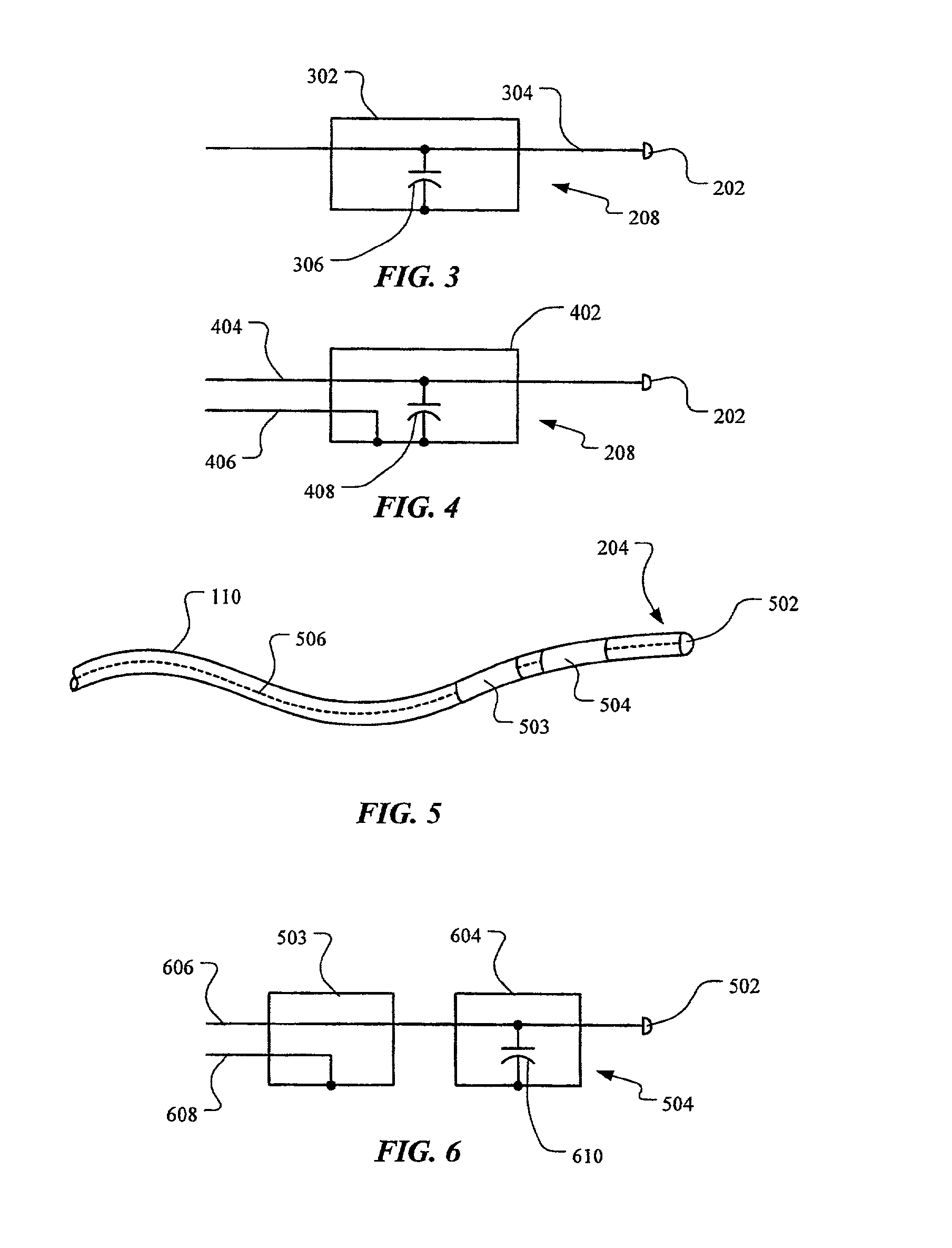
[0028] In a third embodiment, as illustrated in FIGS. 5 and 6, an implantable medical device 102 is a bipolar device in which the tip electrode 502 may serve as a cathode and a first ring electrode 503 may serve as an anode for the pacing, stimulation, or sensing circuitry (not shown) of the implantable medical device 102. In this embodiment, a shunting assembly 504 includes a second ring electrode 604, which is the portion of the shunting assembly 504 visible in FIG. 5. A conductor set 506 includes a tip conductor 606 that extends through the first ring electrode 503 and the second ring electrode 604 to the tip electrode 502. The tip conductor 606 may be a continuous conductor or may be a plurality of conductors that are electrically interconnected. The conductor set 506 further includes a ring conductor 608 extending to the first ring conductor 503. As in the tip conductor 606, the ring conductor 608 may be a continuous conductor or may be a plurality of conductors that are electr...
PUM
 Abstract
Description
Claims
Application Information
 - Generate Ideas
- Intellectual Property
- Life Sciences
- Materials
- Tech Scout
- Unparalleled Data Quality
- Higher Quality Content
- 60% Fewer Hallucinations
Browse by: Latest US Patents, China's latest patents, Technical Efficacy Thesaurus, Application Domain, Technology Topic, Popular Technical Reports.
© 2025 PatSnap. All rights reserved.Legal|Privacy policy|Modern Slavery Act Transparency Statement|Sitemap|About US| Contact US: help@patsnap.com