Radio terminal

a terminal and radio technology, applied in the field of radio terminals, can solve the problems of preventing communication from being performed, breaking the communication link, and difficult to directly apply the proposals described above to local networks such as ad hoc networks

Inactive Publication Date: 2003-05-15
NEC CORP
View PDF5 Cites 45 Cited by
  • Summary
  • Abstract
  • Description
  • Claims
  • Application Information

AI Technical Summary

Benefits of technology

[0013] The third method, which is an application of the method using a distance vector, increments the hop count each time an error packet is received. Increasing the hop count and, thereby, decreasing the priority of a selection path for selecting the best route is efficient on a usual network. However, on a local network where the network quality is decreased in a relatively short time in the mobile environment, the best path cannot be selected simply by increasing the hop count to decrease priority as time goes on.
[0069] FIG. 20 is a diagram showing a simple configuration in which three wireless terminals in the modified embodiment form a route.

Problems solved by technology

A bit error rates, if higher than a predetermined rate, prevents communication from being performed and breaks the communication link.
Therefore, it is difficult to directly apply the proposals described above to local network such as an ad hoc network.
However, the first method is not applicable to a local network such as an ad hoc network described above.
Each time a wireless terminal via which data is sent is changed to another wireless terminal in a local network, a plurality of path searches must be re-attempted as described above and, in addition, the path search processing takes long.
Therefore, in such a network, it is not realistic to create a path table for all terminating ends.
However, if a radio local network such as an ad hoc network, which has no dedicated gateway, is built using the second method, it becomes difficult to search for the best path.
This is because, on a radio network in which the network quality changes in relatively short time, it is impossible to search for the best path based on link information only.

Method used


Image

  • Radio terminal
  • Radio terminal
  • Radio terminal

Examples


Embodiment Construction

[0070] Preferred embodiments of the present invention will now be described in detail.

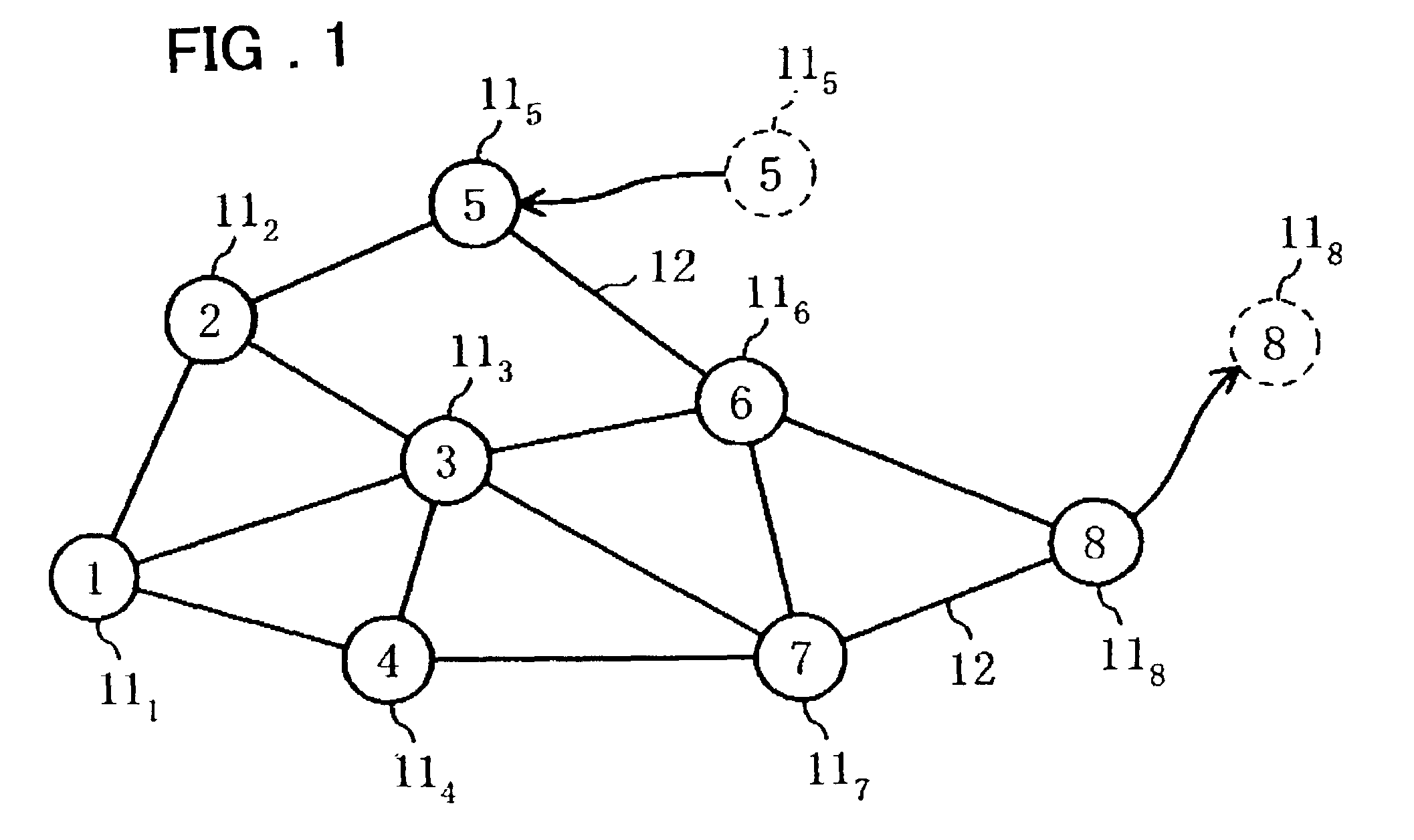
[0071] FIG. 1 illustrates a local network to which terminals according to one embodiment of the present invention is applied. It is assumed that a plurality of wireless terminals 11.sub.1-11.sub.8 are provided in a relatively limited area as shown in the figure. The numerals 1-8 in the circles (.largecircle.), which indicate the terminals 11.sub.1-11.sub.8, represent unique addresses of the terminals. This figure indicates the fifth wireless terminal 11.sub.5 has moved from somewhere else and has joined this local network. Each of the straight lines joining the wireless terminals 11.sub.1-11.sub.8 indicates a link 12 between each two terminals. When the fifth terminal 11.sub.5 has joined this network, the link 12 is created for data communication with other wireless terminals 11 in the network. Conversely, for example, when the eighth wireless terminal 11.sub.8 has left the network, the link 12 is ...


PUM


Abstract

A wireless terminal capable of quickly searching for the best route required for communication in a local network such as an ad hoc network is provided. Each of wireless terminals in the local network sets a bit error rates and a data transfer rate with neighboring wireless terminals and, based on the calculated values, calculates the route weight value of a link to each of the neighboring terminals. To set a route for communication between a wireless terminal and another wireless terminal, the wireless terminal issues a route search command based on the route weight value and sends the route weight value to neighboring terminals. The neighboring terminals also send the route search command sequentially to the next terminal while adding up the route weight value. A wireless terminal at the other end decides the best route from the added up route weight value and sends a response back to the starting point.

Description

[0001] The present invention relates to a wireless terminal, and more particularly to a wireless terminal that can set up a route to a terminal at the other end with which communication is to be established in a local network.[0002] Radio terminals such as portable terminals have become widely used with more and more attention on a local communication among those wireless terminals. A typical such local network is an ad hoc network. An ad hoc network is a local network temporarily created as required. A wireless terminal belonging to the network does not know what terminals are in the network. Nor is there a server that centrally manages the network. The wireless terminals do not have to create a special setting for communication but autonomously recognize surrounding wireless terminals to build a network for information exchange or sharing. On this network, there is a possibility that a wireless terminal suddenly leaves the network. A need therefore exists for a mechanism that can ...

Claims


Application Information

Patent Timeline
Patent Type & Authority Applications(United States)
IPC IPC(8): H04B7/15H04B7/26H04L12/701H04L1/18H04L5/14H04L12/28H04L12/725H04W16/26H04W40/02H04W40/34H04W74/08H04W84/12H04W84/18
CPCH04L1/1809H04L5/1446H04L45/26H04W40/12H04L1/203H04W40/246H04W40/28H04W88/02H04W40/22
Inventor WATANABE, MITSUHIRO
Owner NEC CORP
Why Eureka
Try Eureka