
System and method for generating alert conditions in a surveillance system

a surveillance system and computer system technology, applied in the field of computer system and method for generating alert conditions in the surveillance system, can solve the problems of limited recognition, typically extremely limited, and no image recognition facility in the video surveillance system

Inactive Publication Date: 2003-05-22
ETREPPID TECH
View PDF16 Cites 21 Cited by
  • Summary
  • Abstract
  • Description
  • Claims
  • Application Information

AI Technical Summary

Problems solved by technology

Video surveillance systems typically do not have any facility for image recognition.
Even when a video surveillance system include pattern recognition capability, it is typically extremely limited--for example, a camera may be focused on the license plates of cars passing through a toll booth gate, and the pattern recognition is limited to recognizing letters and digits on the license plate.
For many other applications, more sophisticated types of pattern recognition are desirable but are not readily available in the prior art.

Method used


Image

  • System and method for generating alert conditions in a surveillance system
  • System and method for generating alert conditions in a surveillance system

Examples


Embodiment Construction

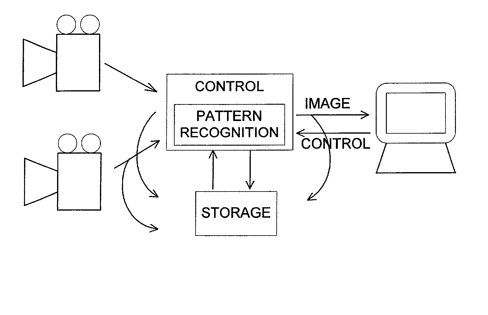
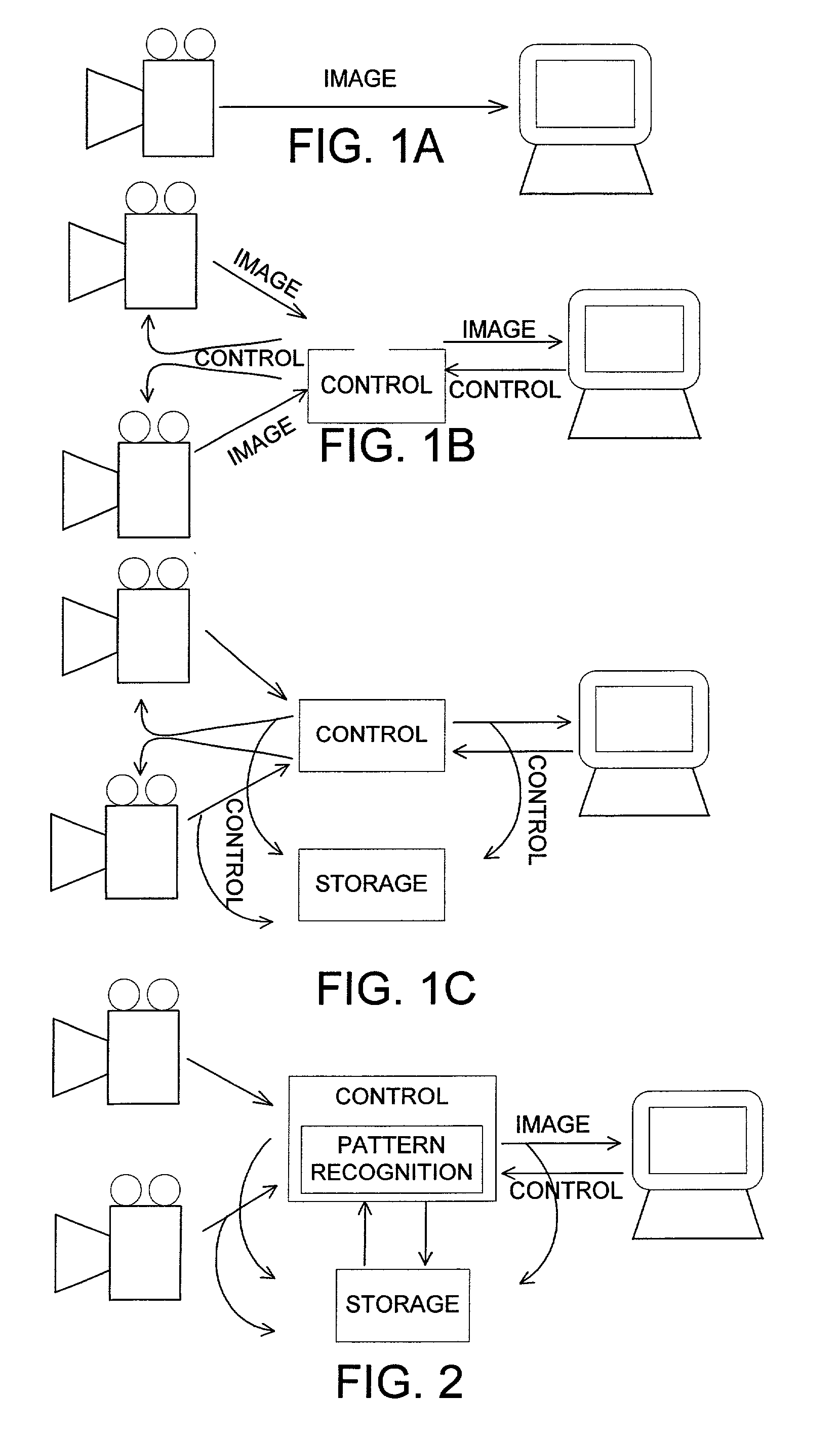
[0014] FIG. 2 shows a video surveillance system according to an embodiment of the present invention. This system is similar to the one shown in FIG. 1C, with the exception that in addition to controlling the positions of the cameras and supplying the camera signals to the monitor, the controller also monitors images produced by the cameras for certain conditions as specified by rules set by the video surveillance system operator, and produces alerts, also called alarms, or the like when one of those conditions is met. Alternatively, the monitoring program need not be in the controller, but may be separate and monitor images in the digital storage device after storage.

[0015] Regardless of where the monitoring is done, the base of the monitoring program lies in its pattern recognition of image features. Typically, pattern recognition as used herein is capable of identifying people based on a shot of their face in an image, etc. Further, the pattern recognition system can also resolve ...


PUM


Abstract

A monitor program in a video surveillance system monitors images coming from one or more surveillance cameras. When an image or set of images satisfies certain conditions, the monitor program takes an appropriate action. For example, in a video surveillance system in a bank, there may be a surveillance camera in the bank's lobby as well as a surveillance camera inside the bank's vault. If, using appropriate pattern recognition techniques, the monitor program recognizes a cleaning person in the lobby doing cleaning, it might not take any action since that would be a legitimate place for the cleaning person to be. If, however, the monitoring system recognized that cleaning person as being in the vault, it might send an alert to the surveillance system operator for further inspection, since cleaning personnel typically should not be in the vault.

Description

[0001] 1. Field of the Invention[0002] The present invention is directed to a computer system and method for generating alert conditions in a surveillance system. More particularly, it is directed to checking images from a camera producing an image stream and determining whether certain events occur in the images from the camera.[0003] 2. Background of the Related Art[0004] Surveillance systems are known in the art. In its simplest form, a surveillance system might essentially consist of an analog video camera hooked up to a remote video monitor as shown in FIG. 1A or a microphone attached to a recorder, or a combination of both. Fort he discussion hereinafter, a camera will be described. The camera is pointed at a spot of interest, e.g., a front door, an automated teller machine, etc., and provides an image of that scene to the monitor. An operator watches the monitor to look for unusual or unauthorized behavior at the scene. If such activity is perceived, the operator takes approp...

Claims


Application Information

Patent Timeline
Patent Type & Authority Applications(United States)
IPC IPC(8): G06K9/00G08B13/196H04N5/76H04N5/77
CPCG06K9/00362H04N5/77H04N5/76G08B13/19615G06V40/10
Inventor MONTGOMERY, DENNIS L.
Owner ETREPPID TECH
Learn More