

Control loop and method for variable speed drive ride - through capability improvement
a technology of variable speed drive and control loop, which is applied in the direction of motor/generator/converter stopper, dynamo-electric converter control, instruments, etc., can solve the problems of system downtime, inability of the inverter to supply the required voltage to the load, and inability to meet the load's operating conditions
- Summary
- Abstract
- Description
- Claims
- Application Information
AI Technical Summary
Problems solved by technology
Method used
Image

Examples
Embodiment Construction
[0001] 1. Field of the Invention
[0002] This invention relates to a control loop and method for enabling variable speed drives (VSDs) with an intermediate DC stage to ride through supply voltage sags.
[0003] 2. Background of the Invention
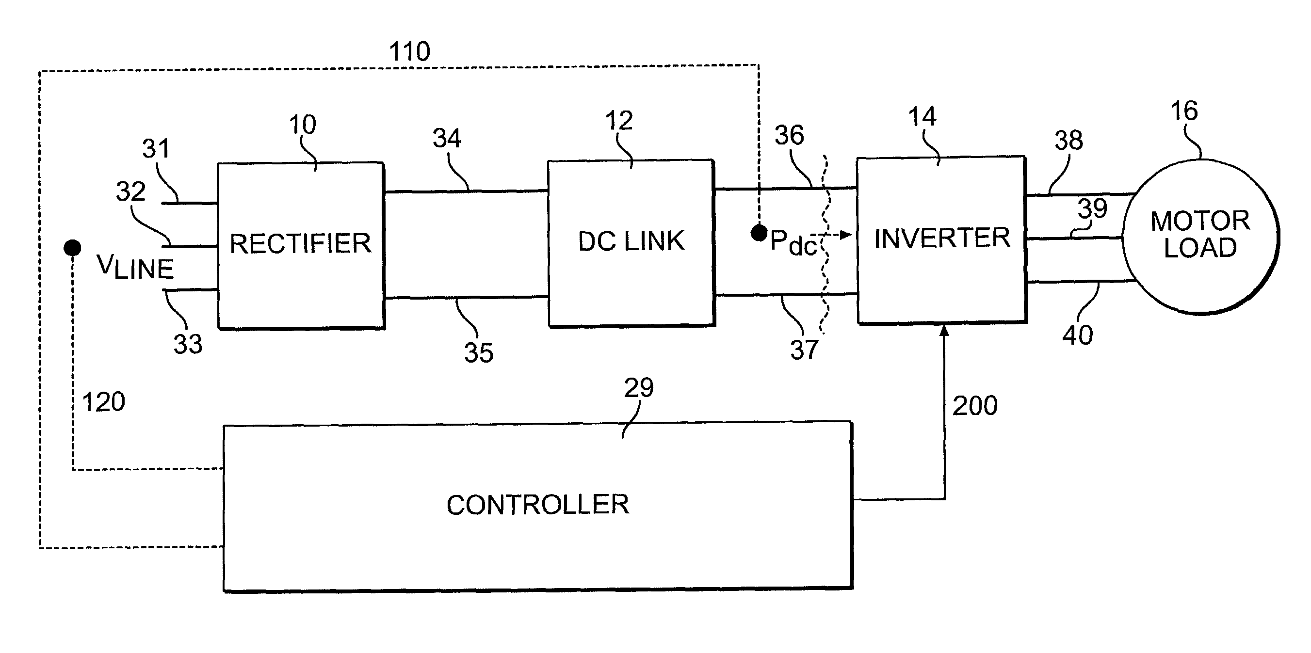
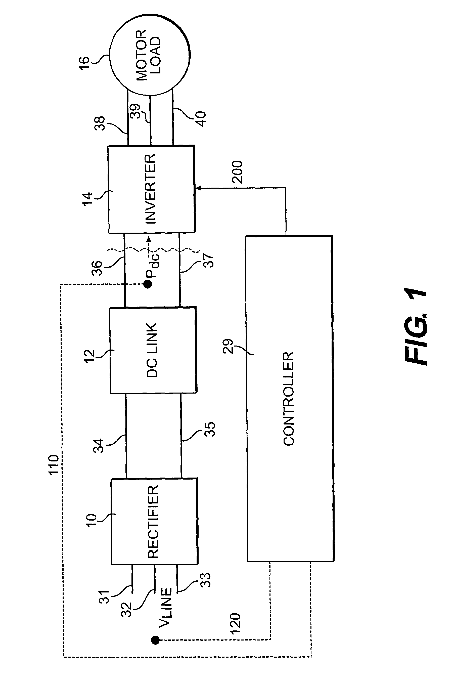
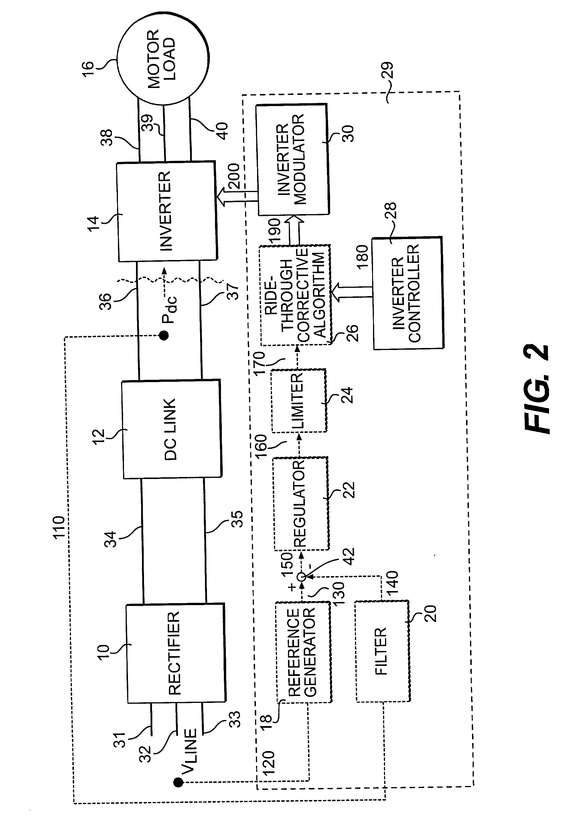
[0004] A typical variable speed drive (VSD) includes three stages, i.e., a rectifier, an intermediate DC link, and an inverter. The rectifying stage converts the fixed-frequency, fixed-voltage input AC power from a power source such as a municipal power company into DC power. The intermediate DC link filters the DC power and has energy storage components, such as capacitors and / or inductors. Finally, the inverting stage converts the DC power into variable-frequency, variable-voltage AC power, supplied to an AC load (typically an induction motor).
[0005] The load can operate properly under given conditions only if appropriate voltage is supplied to it. The ability of a VSD to supply voltage to a load depends on the DC voltage at the DC link of the VSD. ...
PUM
 Abstract
Description
Claims
Application Information