Foundation from bracket and method

a technology of foundation brackets and poured concrete, which is applied in the direction of form/shutter/falseworks, building parts, building material handling, etc., can solve the problems of insufficient manpower and supporting equipment, inconvenient installation, and insufficient labor. , to achieve the effect of reducing labor intensity, reducing labor intensity, and reducing labor intensity

Inactive Publication Date: 2003-06-05
GUSTIN MORRIS HOUSTON
View PDF3 Cites 28 Cited by
  • Summary
  • Abstract
  • Description
  • Claims
  • Application Information

AI Technical Summary

Problems solved by technology

This procedure is tedious, inexact, labor intensive, wasteful, and therefore very expensive in many aspects.
It is very tedious, as the bracing requires many hours to purchase lumber and then to construct the forms and stakes.
Considerable time is needed in cutting and forming sturdy form supports, bracing and stakes.
These forms are very heavy in order to be sufficiently durable and thereby require additional manpower and supporting equipment to position.
When cement is poured into the form, a tremendous amount of pressure is exerted outward against the form enclosure.
Tremendous waste occurs with formation of each new foundation using the current methods.
First, lumber is over purchased in quantity because the science of staking is not consistent and determined by too many variables such as surface and ground type, angle of supports, length of stakes, type of nails used, height of foundation desir

Method used


Image

  • Foundation from bracket and method
  • Foundation from bracket and method
  • Foundation from bracket and method

Examples


Embodiment Construction

. 1-2

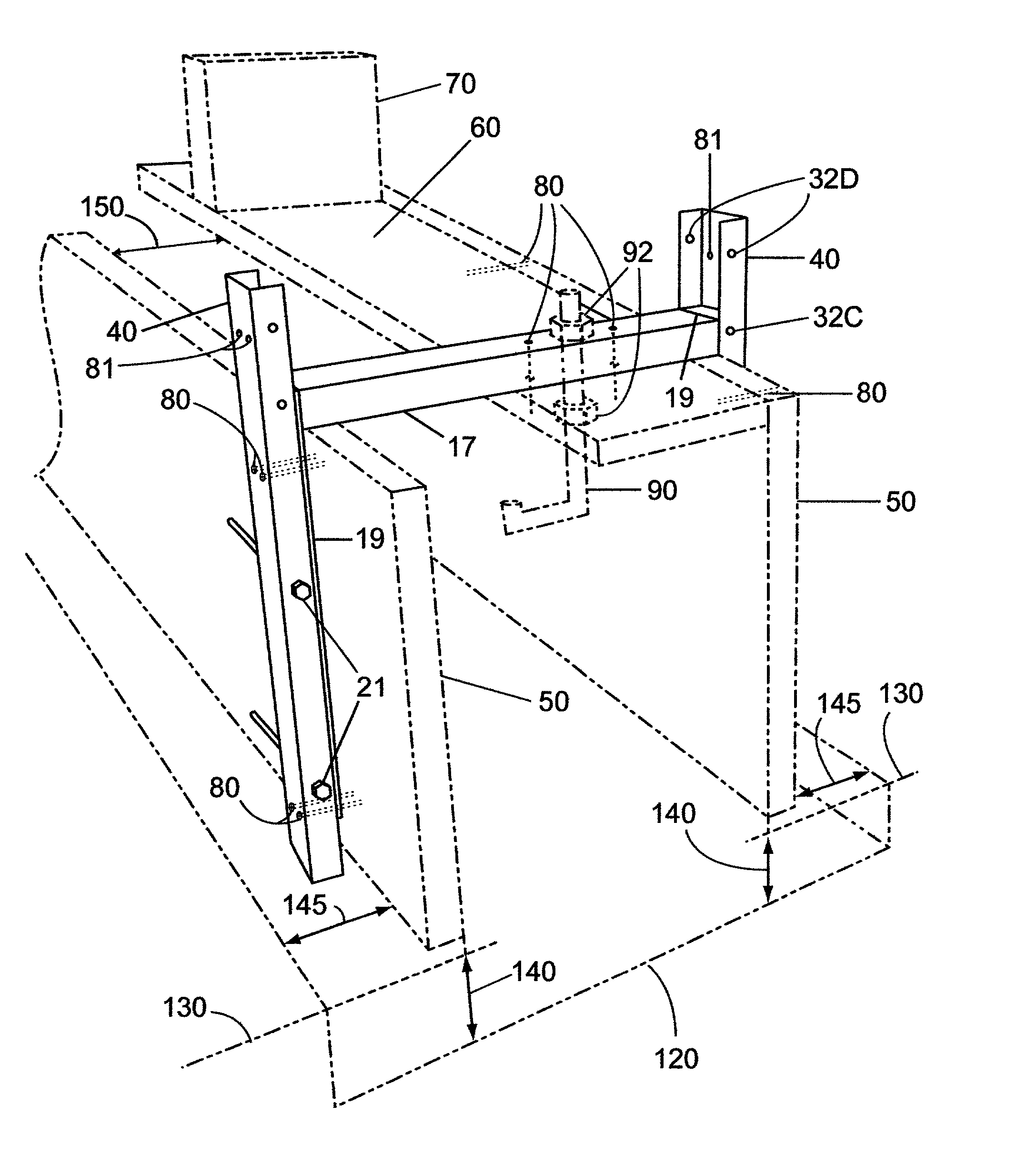
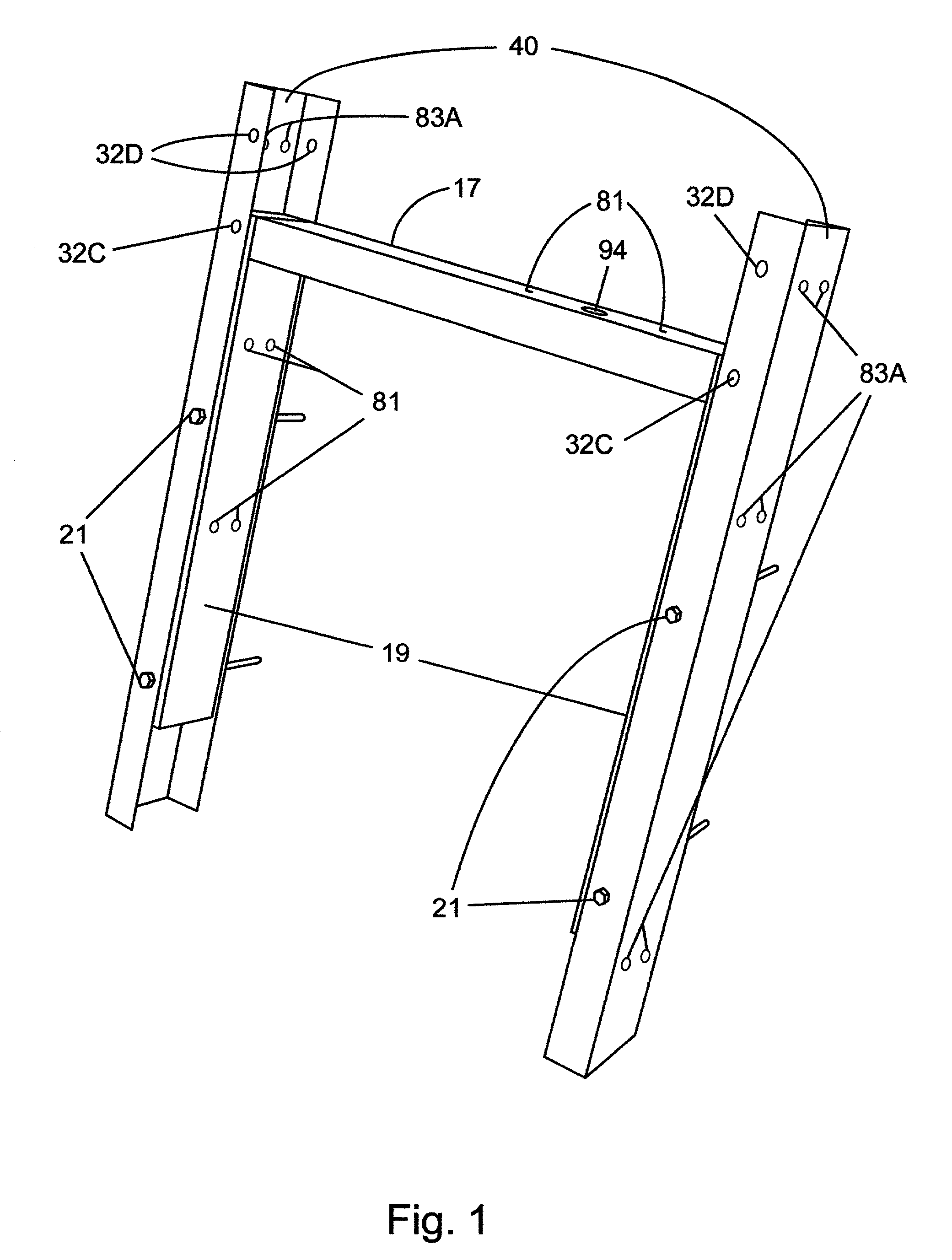
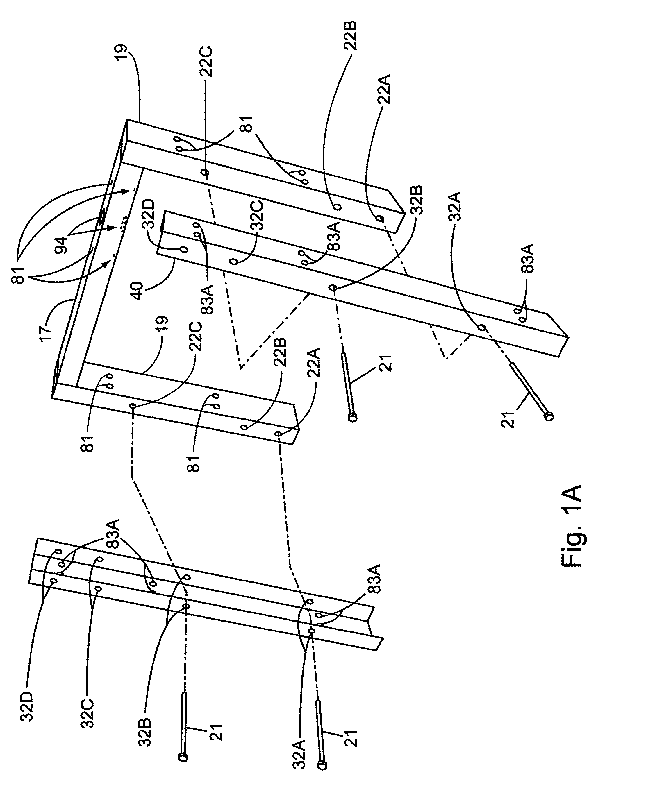
[0042] The invention consists of three parts, a main bracket FIG. 2 (perspective view), two adjustable standard side supports FIG. 3 (perspective view), and two pin bolts 21 on each side to hold the adjustable standard side supports 40 onto the main bracket FIG. 1 and FIG. 1A. FIG. 3 shows one example of a standard side support 40. Standard side supports 40 are universal and interchangeable on the main bracket FIG. 2.

[0043] Conventional tools can be used for drilling, cutting and welding steel to construct the bracket assembly. The main bracket FIG. 2 is formed from rectangular tubing steel of {fraction (1 / 8)} inch (3.275 ) thickness. Each standard side support 40 as seen in FIG. 3 is formed from {fraction (1 / 8)} inch (3.275 mm) thickness steel that fits over the rectangular tubular steel on the outer three sides. Using {fraction (1 / 8)} inch (3.275 mm) as the standard steel thickness, outside dimensions of the rectangular tubular steel measures 2 inches (50.08 mm) wide, by 1 in...


PUM


Abstract

A pre-fabricated building foundation form assembly is installed beneath a pre-existing temporarily supported structure in its final position, and a footing dug below the line of the lowest building timber. A rigid sheet form element is positioned along the upper and outside perimeter side portion of the lowest building timber. The brackets are positioned over the lowest timber and against the sheeting at specified intervals and held in place with connectors. Adjustable supports are attached to the brackets and connectors attach brackets to sheeting. J-bolts along with structural steel are installed. A rigid sheet form element is laterally positioned along the inside perimeter of the inner side of the brackets and held with connectors, which completes the suspended enclosure. A flowable and settable foundation material fills the space within the enclosure and extends essentially continuously upwardly from the footing below the site surface to meet the lower surface of the lowest floor timber to support the building thereon once the foundation material has cured. The footing below the rigid sheet form element has a lateral width greater than the space between the portions of the enclosure to form a foundation footing of suitable width.

Description

[0001] 1. Field of Invention[0002] The invention relates to a poured concrete foundation bracket apparatus, and method of installation thereof, particularly for use with existing buildings or floor assemblies.[0003] This bracket temporarily supports a foundation form for pouring a one up to a three-story foundation. The bracket assembly comprises the main bracket and two adjustable supports. The foundation form bracket assembly is secured to the lowest timber of the building usually referred to as the mudsill and extends over and downward toward the site surface and attaches to rigid sheet panels. The bracket is used to hold and suspend sheet panels so as to create a relatively enclosed space in which a flowable concrete mixture is poured to specifications at an opening left at the top of the enclosure. The form assembly uses a reusable and adjustable bracket that attaches sheet panels rapidly, thus reducing time required preparing the site. The bracket's strength also eliminates th...

Claims


Application Information

Patent Timeline
IPC IPC(8): E02D27/02E04G13/00E04G17/12E04G21/18
CPCE02D27/02E04G21/185E04G17/12E04G13/00
Inventor GUSTIN, MORRIS HOUSTON
Owner GUSTIN MORRIS HOUSTON
Why Eureka
Try Eureka