Fuel injection valve

a fuel injection valve and valve body technology, applied in the direction of fuel injection apparatus, spraying apparatus, charge feed system, etc., can solve the problems of limited armature bore diameter, lack of free flow space for fuel, and large pressure difference between the upper and lower sides of the armature, so as to make it possible for fuel to pass through

Inactive Publication Date: 2003-06-05
ROBERT BOSCH GMBH
View PDF5 Cites 25 Cited by
  • Summary
  • Abstract
  • Description
  • Claims
  • Application Information

AI Technical Summary

Problems solved by technology

What is disadvantageous about the fuel injectors known from the above-named documents is particularly the lack of free flow space for the fuel, which is caused by the positioning of the valve needle in a hollow recess in the armature.
This leads to big pressure differences between the upper and the lower sides of the armature, particularly during movement of the armature, since pressure equalization is hindered.
The diameter of borings in the armature, put there to make it possible for the fuel to pass through, is limited because of the necessary armature pole surface and the low space availability.
It is also disadvantageous that the hydraulic pressure force of the fuel on the armature leads especially to longer valve opening times, which has a corresponding effect on the quantity of fuel metered in.
On the other hand, due to fluctuations in the pressure difference, for example, in the case of different temperatures of the fuel injector, and viscosity differences resulting from this, variations in the switching time of the fuel injector are caused, which, in addition to the increased length of the switching times, lead to metering in irregular quantities of fuel.

Method used


Image

  • Fuel injection valve
  • Fuel injection valve
  • Fuel injection valve

Examples


Embodiment Construction

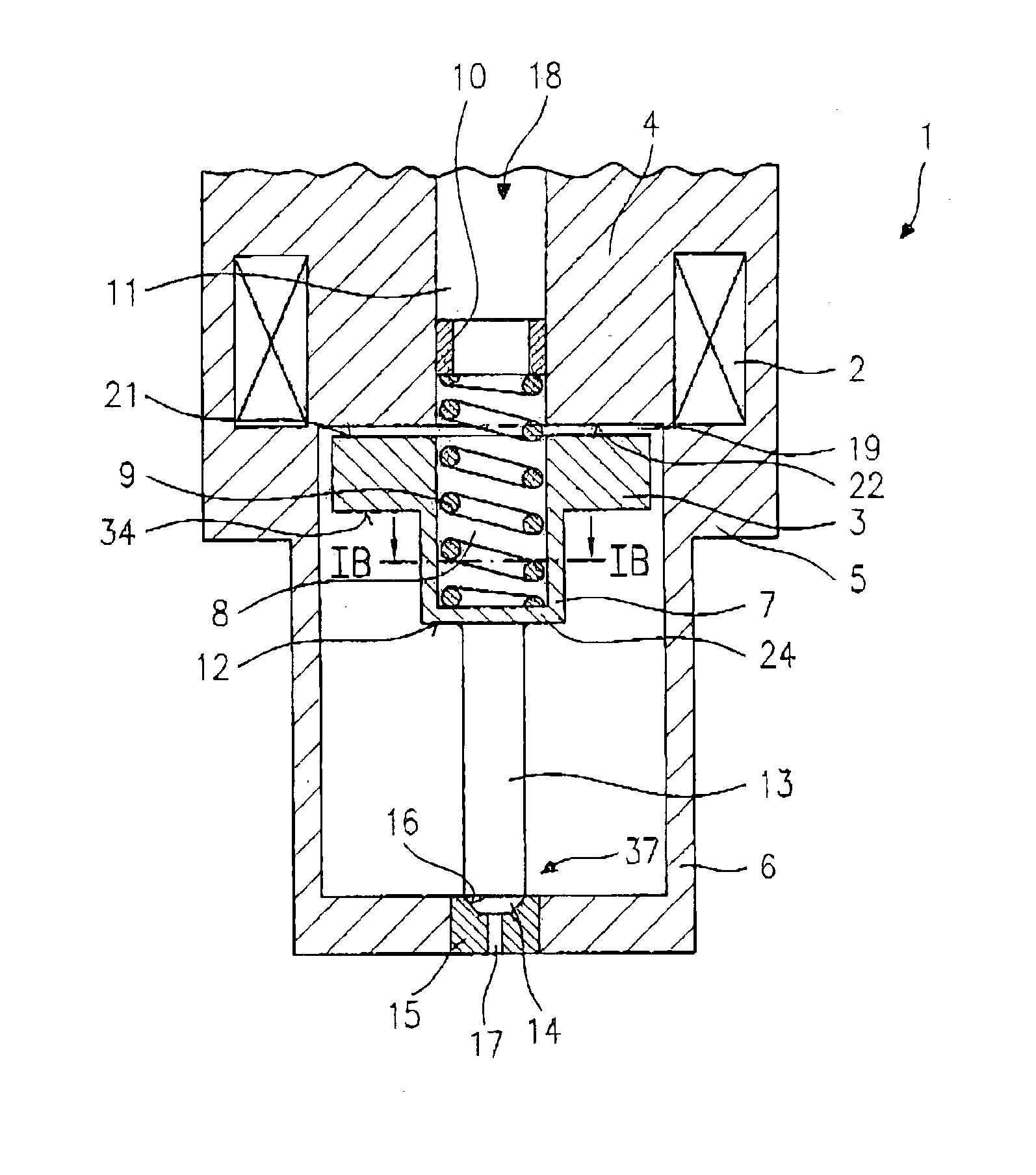
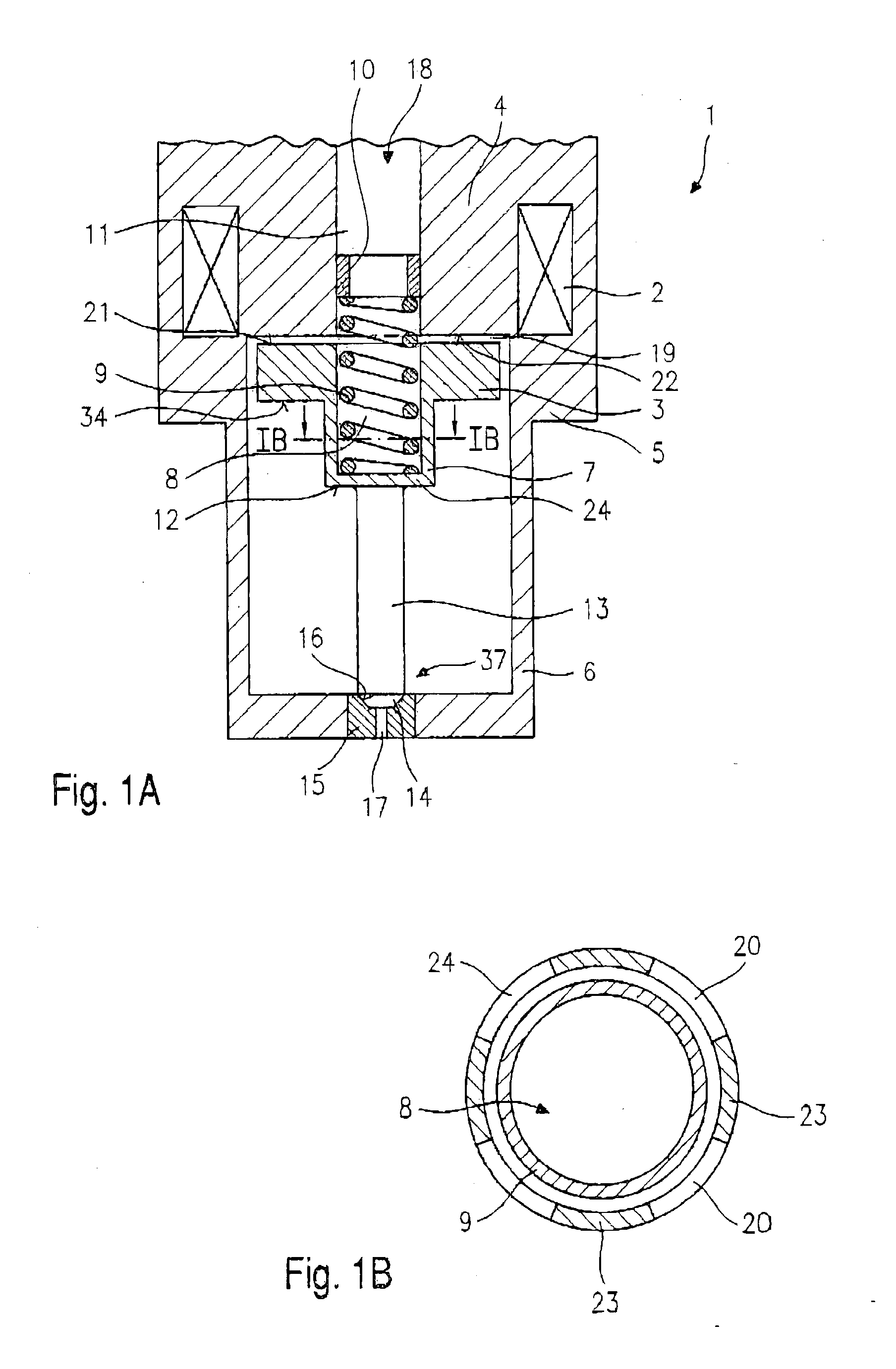
[0018] FIG. 1 shows a longitudinal section through a first exemplary embodiment of a fuel injector 1 according to the present invention, as a segment of a very much schematic sectional representation.

[0019] Fuel injector 1 has a magnetic coil 2 which acts together with an armature 3. Magnetic coil 2 acts together with an internal pole 4 and an external pole. External pole 5 continues on the downstream side in a valve housing 6.

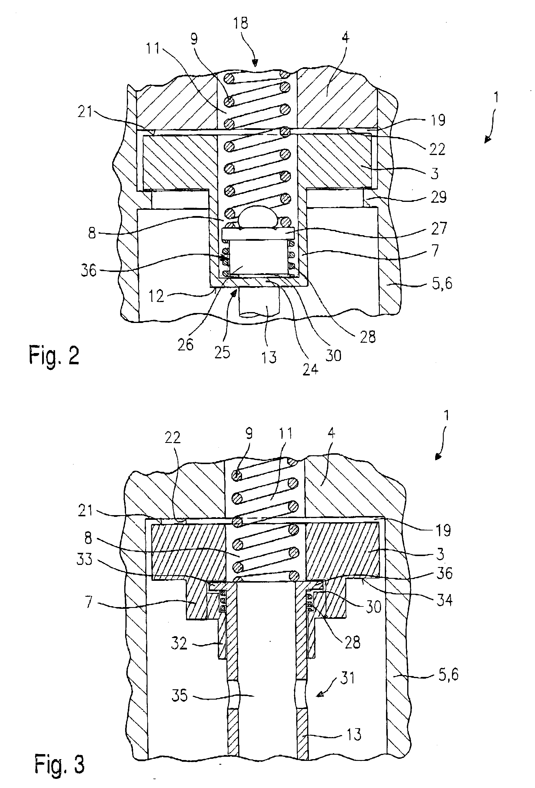
[0020] Armature 3 has an extension 7 which is formed as a hollow cylinder and is positioned at the downstream side 34 of armature 3. Extension 7 has a bottom portion 24, which closes off extension 7 on the downstream side. In an inner recess 8, which is developed in armature 3 and extension 7, there is a resetting spring 9. Resetting spring 9 is prestressed by adjusting sleeve 10 pushed into internal pole 4 in a hollow recess 11 of internal pole 4.

[0021] A valve needle 13 is supported at a downstream end 12 of the extension 7. Valve needle 13 is preferably wel...


PUM


Abstract

A fuel injector (1), particularly a fuel injector (1) for fuel injection systems of internal combustion engines, has a magnetic coil (2), an armature (3) acted upon in a closing direction by a resetting spring (9) and a valve needle connected to the armature by force-locking for operating a valve-closure member (14), which forms a sealing seat together with a valve-seat surface (16). The armature (3) has a pot-shaped axial extension (7), in which at least one cutout (20) is formed.

Description

BACKGROUND INFORMATION[0001] The present invention is based on a fuel injector of the type set forth in the main claim.[0002] As an example, from DE 196 26 576 A1 an electromagnetically operable fuel injector is known, in which, for the electromagnetic actuation, an armature cooperates with an electrically energizable magnetic coil, and the lift of the armature is transmitted to a valve-closure member via a valve needle. The valve-closure member interacts with a valve-seat surface to form a sealing seat. Several fuel channels are provided in the armature. The armature is reset by a resetting spring.[0003] An electromagnetically operable fuel injector is also known from DE 195 03 821 A1, in which an armature also cooperates with an electrically energizable magnetic coil. The lift of the armature is transmitted to a valve-closure member by a valve needle.[0004] What is disadvantageous about the fuel injectors known from the above-named documents is particularly the lack of free flow s...

Claims


Application Information

Patent Timeline
Patent Type & Authority Applications(United States)
IPC IPC(8): F02M51/08F02M51/06F02M61/10
CPCF02M51/0653F02M51/066F02M51/0657
Inventor SEBASTIAN, THOMASBOEE, MATTHIAS
Owner ROBERT BOSCH GMBH
Why Eureka
Try Eureka