Apparatus and method of continuous sintering a web material

Inactive Publication Date: 2003-06-05
USF FILTRATION & SEPARATIONS GROUP
View PDF0 Cites 6 Cited by
  • Summary
  • Abstract
  • Description
  • Claims
  • Application Information

AI Technical Summary

Problems solved by technology

The elevated temperature is sufficient to affix the elemental metallic or ceramic components together either by melting the surface of the elemental metallic or ceramic components or by surface interaction but is insufficient to melt the individual elemental metallic or ceramic components.
The first disadvantage of the batch and the continuous-batch sintering processes was the limitation of the physical size of the fibrous media.
The second disadvantage of the batch and the continuous-batch sintering processes was the variations in the weight produced by the stack of sheets of fibrous media and the refractory material.
This caused variation in the thickness of the sheets of the fibrous media.
A third disadvantage of the batch and the cont

Method used


Image

  • Apparatus and method of continuous sintering a web material
  • Apparatus and method of continuous sintering a web material
  • Apparatus and method of continuous sintering a web material

Examples


Embodiment Construction

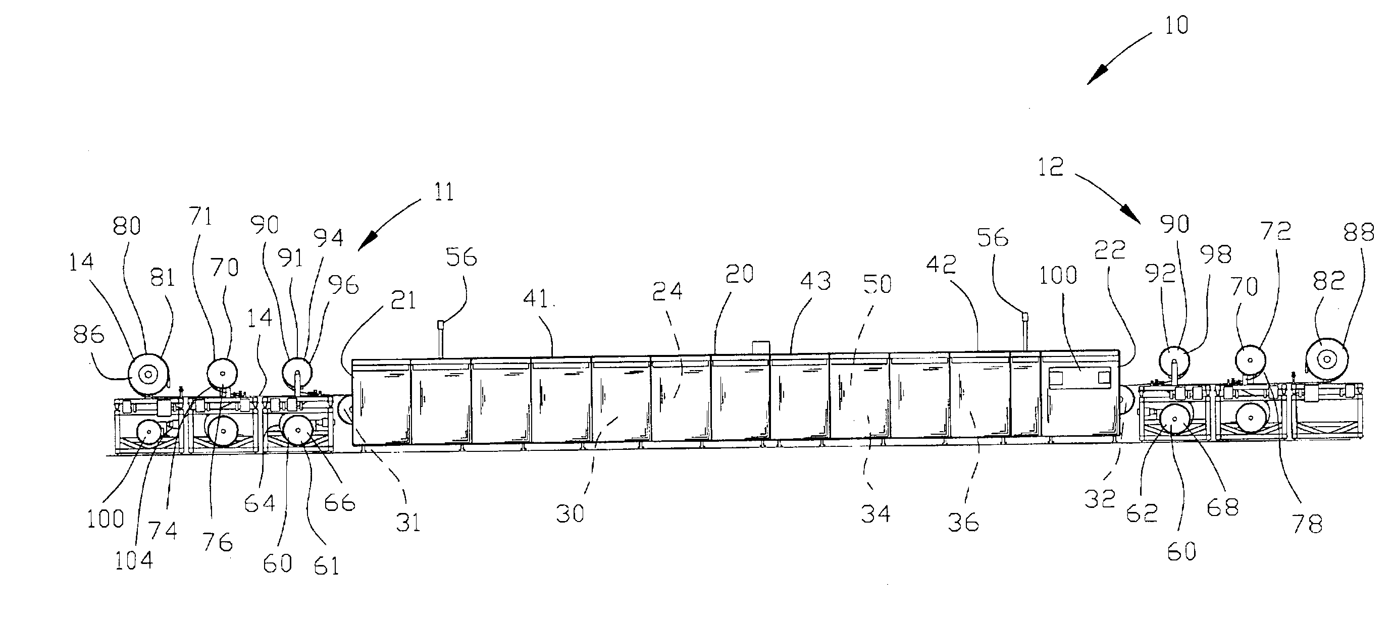
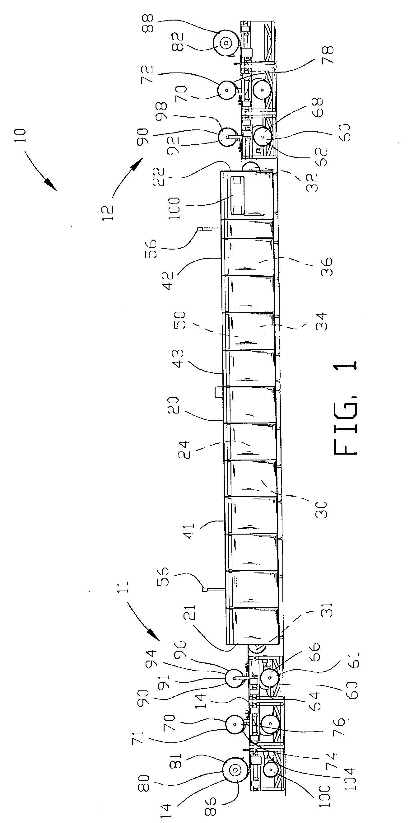
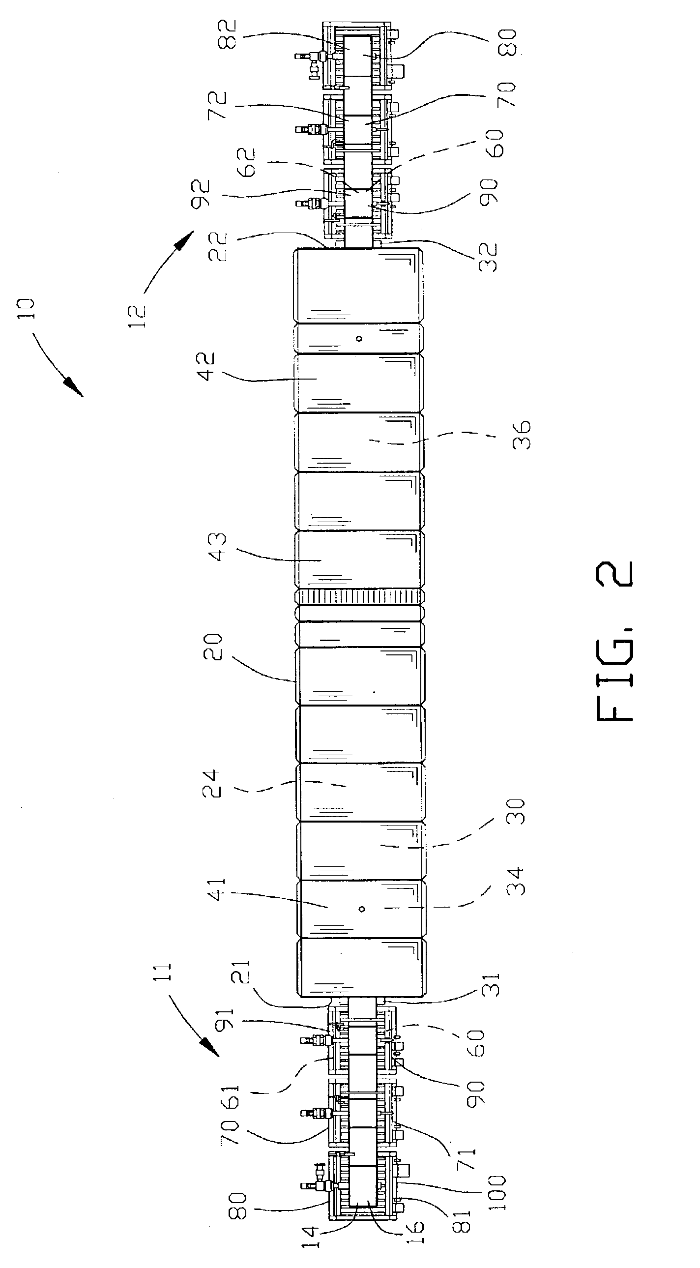
[0078] FIGS. 1 and 2 are side and top elevational views of a first embodiment of an apparatus 10 incorporating the present invention. The apparatus 10 extends between an input portion 11 and an output portion 12 for continuously sintering a web material 14 with a sintering furnace 20. The sintering furnace 20 comprises an open furnace input 21 and an open furnace output 22. Preferably, the sintering furnace 20 comprises a tunnel 24 extending between the open furnace input 21 and open furnace output 22.

[0079] A furnace conveyor 30 comprises an input drum 31 and output drum 32 with an endless belt 34 disposed therebetween. The input drum 31 and the output drum 32 are located adjacent to the open furnace input 21 and the open furnace output 22 with endless belt 34 extending through the sintering furnace 20. The furnace conveyor 30 continuously moves from the open furnace input 21 to the open furnace output 22.

[0080] The sintering furnace 20 includes an input zone 41 and an output zone ...


PUM

PropertyMeasurementUnit
Forceaaaaaaaaaa
Tensionaaaaaaaaaa
Refractoryaaaaaaaaaa

Abstract

An apparatus and method is disclosed for continuously sintering a web of multiple layers of media material with a sintering furnace. In a preferred form of the invention, a plurality of web media materials are interposed between refractory materials and are simultaneously sintered in the sintering furnace. Following sintering the plurality of web media materials are separated from the refractory materials and the web media materials are independently rolled onto a plurality of output rollers. A tension device applies a tension acting upon opposed ends of the refractory materials for maintaining a constant tension therebetween for maintaining a constant force on the upper and lower surfaces of the plurality of media materials.

Description

[0001] This is a continuation-in-part of U.S. patent application Ser. No. 09 / 437,803 filed Nov. 10, 1999 now U.S. Pat. No. 6,437,803. All subject matter set forth in application Ser. No. 09 / 437,803 is hereby incorporated by reference into the present application as if fully set forth herein.[0002] 1. Field of the Invention[0003] This invention relates to heat treating, and more particularly to an apparatus and method of continuously sintering a web material with a sintering furnace wherein the web material may be a matrix of fine metallic fibers forming a porous media.[0004] 2. Description of the Related Art[0005] The prior art has known various types of devices for sintering a metallic or ceramic object or the like. The metallic or ceramic object is typically made from a matrix of elemental metallic or ceramic components. In the sintering process, the metallic or ceramic object is placed within a heated furnace elevated to a temperature sufficient to affix the elemental components ...

Claims


Application Information

Patent Timeline
IPC IPC(8): B22F3/00C21D9/56F27B9/02F27B9/04F27B9/24F27B9/38F27B9/40F27B21/00F27D3/00F27D3/12F27D21/00
CPCB22F3/003B22F2999/00F27D2021/0092F27D2003/121C21D9/564F27B9/029F27B9/047F27B9/243F27B9/38F27B9/40F27B21/00F27D3/00B22F5/006B22F3/002
Inventor HREZO, JOSEPH R.JOYCE, JOHN F.
Owner USF FILTRATION & SEPARATIONS GROUP
Why Eureka
Try Eureka