An illumination method and apparatus for projection system

a projection system and illumination method technology, applied in the field of projection systems, can solve the problems of not only increasing the cost of the field lens, but also the volume of the whole projection system, and failing to meet the requirements of light weight, slimness and compactness, so as to reduce the loss of illumination, increase the efficiency of illumination, and reduce the volume

Inactive Publication Date: 2003-06-12
CORETRONIC
View PDF0 Cites 9 Cited by
  • Summary
  • Abstract
  • Description
  • Claims
  • Application Information

AI Technical Summary

Benefits of technology

0007] One object of the present invention is to provide an illumination method and apparatus for projection system which can reduce the loss of illumination so as to increase the efficiency of the illumination.
0008] The other object of the present invention is to provide an illumination method and apparatus for projection system which can reduce the volume and lower the cost of the projection system.
0009] To achieve the above mentioned objectives, the present invention mainly comprises an illumination system and an imaging system, wherein the illumination system generates an incident light beam and, by means of reflection with a reflecting lens, projects it from above in front of the field lens into the first surface of the field lens fronting the projection lens set, then through the field lens, and onto the light valve of the imaging system. The geometric center of the light valve is located at the underside of the optical axis of the second surface adjacent to the corresponding side of the first surface of the field lens, allowing the geometric center of the transmissive area created by the projection of the light beam into the field lens to be much closer to the optical axis of the field lens than the geometric center of the light valve is, thus ensuring that the transmissive area is contained within the optimized area on the field lens, and reduces the amount of distortion generated in the light spot by the light beam coming in through the field lens. The light beam is then further reflected, by means of reflection with the array of micro-mirrors poised on the light valve to differentiate the angles of reflection at ON-state or OFF-state, through the field lens, then into or away from the projection lens set, to be selectively projected onto the screen.

Problems solved by technology

This not only increases the cost of the field lens, but also the volume of the whole projection system, failing to meet the requirements in terms of light weight, slimness and compactness.

Method used


Image

  • An illumination method and apparatus for projection system
  • An illumination method and apparatus for projection system
  • An illumination method and apparatus for projection system

Examples


Embodiment Construction

[0020] An embodiment of the present invention, along with the techniques and methods applied to fulfill the above-mentioned objects and with its effectiveness, will now be described in detail with reference to the drawings.

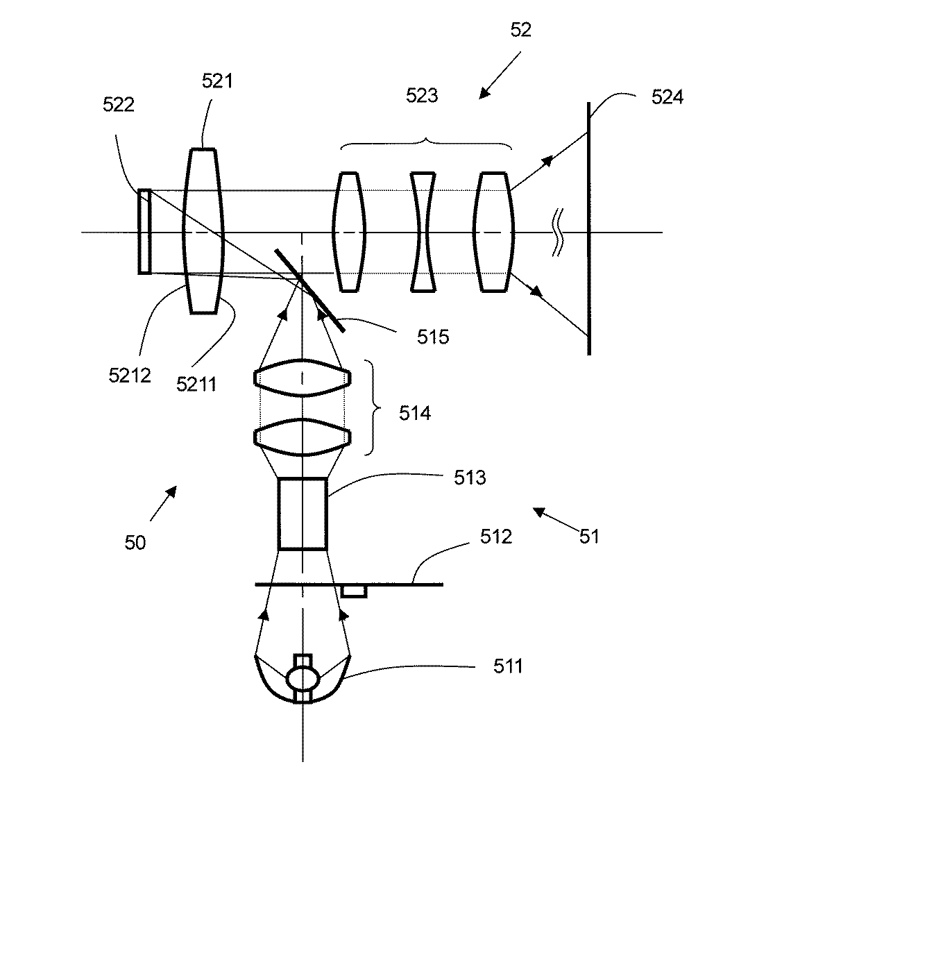
[0021] Illustrated in FIG. 3 is a preferred embodiment of the illumination method and apparatus for projection system of the present invention, wherein the projection system 50 includes an illumination system 51 and an imaging system 52, whereby a light beam generated by the illumination system 51 is reflected onto the imaging system 52, and it is then decided by the imaging system 52 whether or not it is to be projected onto the screen 524.

[0022] The illumination system 51 includes a light source 511, a color-generating device 512 (such as color wheel, filter), a uniform device 513 (such as integrated rod, lens array), an illumination lens set 514 (such as converge lens, relay lens), a reflecting lens 515 (such as reflecting mirror, prism), and a field lens 521. ...


PUM


Abstract

Abstract of Disclosure The present invention mainly includes an illumination system and an imaging system, wherein the illumination system generates an incident light beam, and, by means of reflection with a reflecting lens, projects it from above in front of the field lens, into the first surface of the field lens fronting the projection lens set, then through the field lens, and onto the light valve of the imaging system, wherein the geometric center of the light valve is located at the underside of the optical axis of the second surface adjacent to the corresponding side of the first surface of the field lens, allowing the geometric center of the transmissive area created by the projection of the light beam into the field lens to be much closer to the optical axis of the field lens than the geometric center of the light valve is, thus ensuring that the transmissive area is contained within the optimized area on the field lens, while reducing the amount of distortion generated in the light spot by the light beam coming in through the field lens, wherein the said light beam is then further reflected, by means of reflection with the array of micro-mirrors poised on the light valve to differentiate the angles of reflection at ON-state or OFF-state, through the field lens, then into or away from the projection lens set, and is selectively projected onto the screen, so as to improve illumination efficiency, while lowering the cost and reducing the volume.

Description

Background of Invention[0001] 1.Field of the Invention[0002] The present invention relates to a projection system, and more particularly, to an illumination method and apparatus for the projection system.[0003] 2.Descriptions of the Prior Art[0004] There have been many significant achievements accomplished in every branch of the hi-tech industries in recent years. Developments in the field of optical-electronics have been particularly rapid. Digitalized electronic components, such as digital micro-mirror device (DMD) as a light valve are gradually applied in projection systems which require light weight, slimness, and compactness. The light valve consists of an array of inclinable pixel mirrors with a diagonal rotation within an angle range of .+-.12.degree.. When the inclinable pixel mirrors reflect an incident beam onto an screen, this is referred to as an ON-state; when they reflect an incident beam away from the screen, this is referred to as an OFF-state; when they parallel the...

Claims


Application Information

Patent Timeline
Patent Type & Authority Applications(United States)
IPC IPC(8): G02B26/08G02B27/18G03B21/00H04N5/74H04N9/31
CPCH04N5/7458H04N9/3197H04N9/3114
Inventor WANG , SZE-KE
Owner CORETRONIC
Why Eureka
Try Eureka